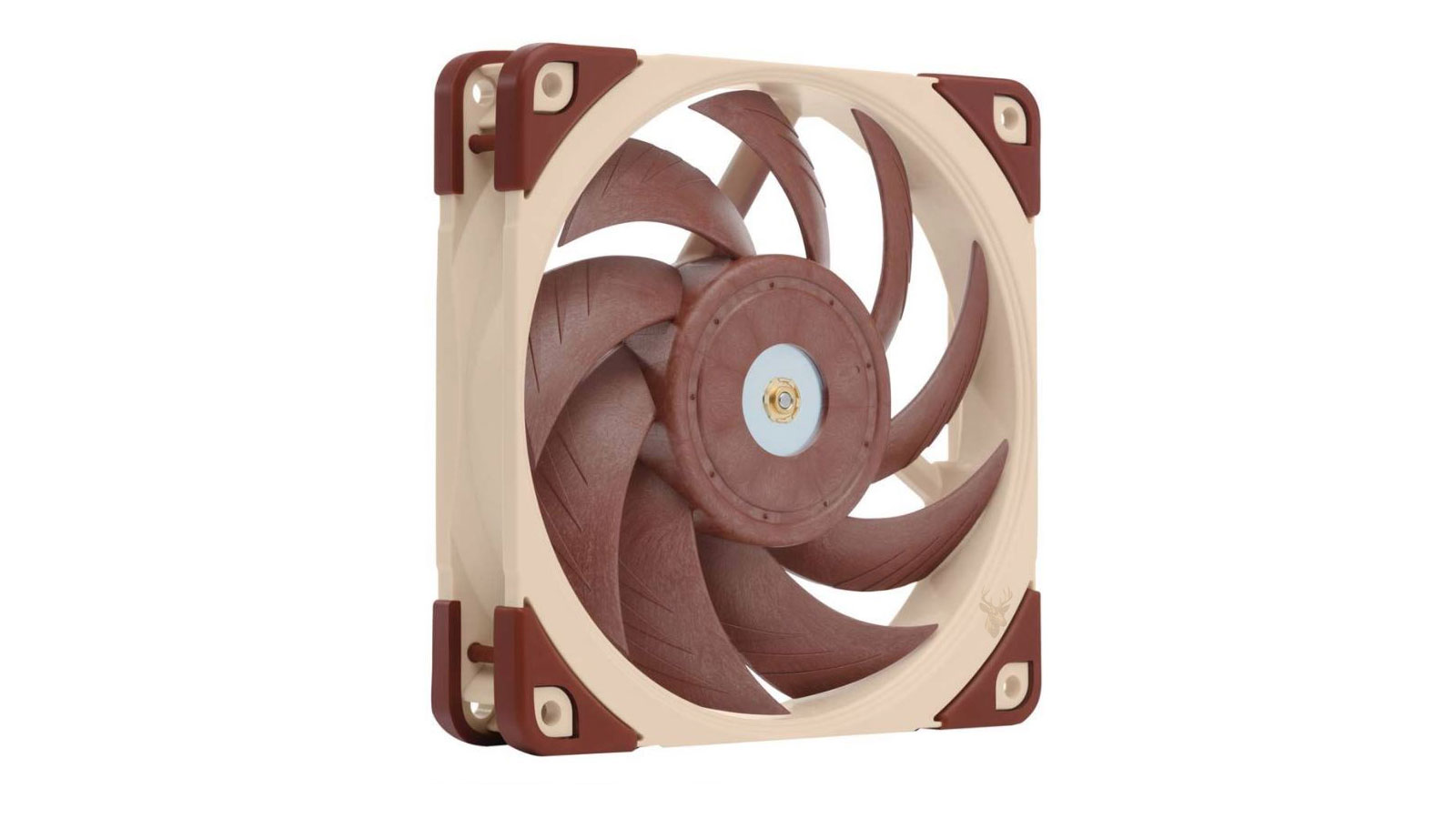
Understanding How Modern Computer Fans Regulate Cooling
Computer cooling fans are designed to move air through a system while producing only as much noise as necessary. Rather than operating at maximum speed all the time, most modern computers automatically adjust fan speed based on component temperatures and workload. Two primary methods are used to accomplish this: DC (Direct Current) voltage control and PWM (Pulse Width Modulation) control.
Although both systems serve the same purpose, they operate differently and require compatible hardware. Understanding these differences helps explain why some fans offer more precise speed adjustments, why replacing a fan with the wrong type can create unexpected behavior, and how motherboard settings influence overall cooling performance.
Why Fan Speed Changes During Normal Use
When a computer is idle, processors and graphics hardware generate relatively little heat. As applications become more demanding, temperatures increase and the cooling system responds by increasing airflow. Once temperatures fall again, the fans gradually slow down.
This automatic adjustment helps reduce unnecessary noise, lowers power consumption, and minimizes wear on cooling components without sacrificing system stability.
What Is a DC Fan?
A DC fan controls its speed by changing the voltage supplied to the motor. Lower voltage causes the fan to rotate more slowly, while higher voltage allows it to spin faster. This method has been used in desktop computers for many years and remains common in certain systems.
Most DC computer fans use a three-pin connector. The pins normally provide power, ground, and a tachometer signal that reports the fan’s rotational speed back to the motherboard.
- Power supply voltage controls fan speed.
- Three-pin connector is commonly used.
- Motherboard can monitor RPM through the tachometer signal.
- Simple and widely compatible design.
What Is a PWM Fan?
PWM stands for Pulse Width Modulation. Instead of changing the voltage supplied to the motor, a PWM fan receives a steady 12-volt power source while a separate control signal rapidly switches the motor on and off. By varying the timing of these pulses, the motherboard controls the fan’s effective speed with much greater precision.
This design allows the fan to operate reliably across a wider range of speeds while maintaining stable motor performance.
The Fourth Wire Makes the Difference
PWM fans typically use a four-pin connector. The additional pin carries the PWM control signal from the motherboard to the fan.
| Fan Type | Typical Connector | Speed Control Method |
|---|---|---|
| DC Fan | 3-pin | Variable voltage |
| PWM Fan | 4-pin | Pulse Width Modulation signal |
Both Types Can Report Their Speed
Whether a system uses DC or PWM control, most motherboard fan headers can monitor the fan’s RPM through the tachometer signal. This allows the BIOS or operating system to verify that cooling fans are operating correctly and to generate warnings if a fan stops unexpectedly.
Fan speed monitoring is separate from fan speed control. A motherboard may successfully read a fan’s RPM even if the selected control mode is not ideal for that particular fan type.
How DC Fan Speed Control Works
A DC fan receives less voltage when the motherboard wants it to spin more slowly. As the voltage increases, the motor gains speed and produces more airflow. The motherboard continuously adjusts this voltage according to the temperature targets defined in the BIOS or fan-control software.
One limitation of voltage control is that every fan has a minimum operating voltage. If the voltage drops too far, the motor may slow unevenly, stall, or fail to start after the computer has been turned on.
PWM Control Uses a Duty Cycle
A PWM fan receives a control signal described by its duty cycle. A higher duty cycle tells the fan to spend more time powered during each rapid pulse sequence, which increases its speed. A lower duty cycle reduces the effective motor speed.
For example, a fan operating at a 50 percent duty cycle does not necessarily spin at exactly half of its maximum RPM. The final speed depends on the fan motor, controller design, and minimum supported range.
PWM Fans Usually Offer Better Low-Speed Control
Because the motor continues receiving a stable 12-volt supply, PWM fans can often operate more consistently at low speeds than comparable DC fans. This makes them useful in systems designed to remain quiet during light workloads.
Better low-speed control does not automatically mean that every PWM fan is quieter. Bearing quality, blade design, fan size, mounting position, and airflow restriction also affect noise.
Motherboard Fan Headers May Support Both Modes
Many modern motherboard fan headers can operate in either DC or PWM mode. The selected setting tells the motherboard whether to regulate voltage or send a dedicated PWM control signal.
Some motherboards detect the connected fan automatically, while others require the control mode to be selected manually in the BIOS. Automatic detection is convenient, but it does not always identify every fan correctly.
Incorrect Control Mode Can Cause Unexpected Behavior
If a three-pin DC fan is connected to a header configured only for PWM control, it may run at full speed because its supply voltage remains fixed. The motherboard can still read the RPM signal, but it may not be able to reduce the fan speed.
A four-pin PWM fan connected to a header configured for DC control may still respond because the motherboard changes the supply voltage. However, this bypasses the fan’s intended control method and may reduce the available speed range.
A fan can spin normally and report its RPM while still being configured with the wrong speed-control method.
Three-Pin Fans Can Connect to Four-Pin Headers
The first three electrical positions are generally shared between standard three-pin and four-pin computer fan connectors. This allows many three-pin fans to fit onto four-pin motherboard headers while leaving the PWM control pin unused.
The connector includes guides that help maintain the correct alignment. Forcing it into the wrong position can bend pins or prevent the fan from receiving power.
Four-Pin Fans Can Also Use Some Three-Pin Headers
A PWM fan can often be connected to a three-pin header, but the dedicated PWM control wire will not be used. The fan may run at full speed, or the motherboard may attempt to control it by varying the voltage if that feature is available.
Compatibility therefore includes more than whether the connector physically fits. The motherboard manual should be checked to confirm how each header controls fan speed.
CPU and Case Fan Headers May Behave Differently
Motherboards commonly provide separate headers for the CPU cooler, case fans, pumps, and optional cooling zones. These headers may support different current limits, monitoring rules, and control modes.
- CPU fan headers may trigger a startup warning if no RPM is detected.
- Case fan headers may offer more flexible temperature-source settings.
- Pump headers may run at full speed by default.
- High-current headers may support several fans through a splitter.
Fan Curves Determine When Speed Changes
A fan curve links temperature readings to specific fan speeds. At low temperatures, the fan may operate slowly. As the selected component becomes warmer, the motherboard raises the voltage or PWM duty cycle to increase airflow.
A gradual curve usually produces smoother noise levels, while an aggressive curve responds more quickly to temperature changes. The best setting depends on the hardware, cooling capacity, and acceptable noise level.
The Temperature Source Matters
CPU fans are normally controlled by processor temperature, while case fans may respond to the CPU, motherboard, graphics area, or another available sensor. A poorly selected temperature source can make a fan react too often or remain slow while another component becomes hot.
For example, a case fan controlled only by CPU temperature may not increase enough during a graphics-heavy workload if the processor remains relatively cool.
Rapid Fan Speed Changes Can Be Distracting
Modern processors can change temperature very quickly during short bursts of activity. If the fan curve reacts immediately to every small temperature increase, the fan may repeatedly speed up and slow down during ordinary tasks.
Many motherboards provide response-delay or smoothing settings. These allow the fan to wait briefly before changing speed, reducing unnecessary fluctuations without preventing a response to sustained heat.
Minimum Fan Speed Must Remain Reliable
Reducing fan speed can improve quiet operation, but the setting must remain high enough for the fan to start consistently. A fan that continues spinning at a very low setting may still fail to begin rotating from a complete stop at that same level.
Fan calibration utilities can help identify the practical minimum speed, but the result should be tested through shutdowns, restarts, and cold starts before it is trusted.
Fan Size Influences Airflow and Noise
Larger fans can usually move the same amount of air at a lower rotational speed than smaller fans. This often allows them to cool a computer with less noticeable noise, provided the case supports the larger mounting size.
Fan size does not determine whether a fan uses DC or PWM control. Both three-pin DC and four-pin PWM models are available in common computer fan sizes.
Bearing Design Also Affects Fan Performance
The internal bearing supports the rotating fan assembly. Sleeve, ball, fluid-dynamic, and other bearing designs can differ in noise, durability, cost, and suitability for different mounting positions.
A high-quality DC fan may operate more quietly than a poorly designed PWM fan. The control method is only one part of overall fan quality.
Fan Splitters Share One Control Signal
A splitter allows multiple fans to connect to one motherboard header. Fans attached to the same splitter usually receive the same voltage or PWM control signal, so they increase and decrease speed together.
Only one fan normally returns its RPM signal through a standard splitter. Combining multiple tachometer signals on the same header could prevent the motherboard from reading fan speed correctly.
The Header Current Limit Must Not Be Exceeded
Every motherboard fan header has a maximum current rating. Connecting too many fans through a passive splitter can overload the header, especially when the fans first start and briefly draw more current.
The fan label or technical specifications should list the current requirement. The combined demand of all connected fans should remain below the limit stated in the motherboard manual.
Powered Fan Hubs Reduce Load on the Motherboard
A powered fan hub receives electricity directly from the computer’s power supply while using a motherboard header only for control and speed monitoring. This makes it useful when several case fans need to follow the same fan curve.
Some hubs support only PWM fans, while others provide voltage control or fixed-speed outputs. Their specifications should be checked before installation.
Fans Running at Full Speed May Be Misconfigured
A fan that suddenly begins running at maximum speed is not always failing. The motherboard may have reset its settings, selected the wrong control mode, lost access to a temperature sensor, or detected that another fan has stopped.
- The header is set to PWM mode for a three-pin DC fan.
- The fan curve has been reset to a performance setting.
- The fan is connected to a pump header configured for full speed.
- The temperature source is reporting unusually high readings.
- Fan-control software is overriding the BIOS settings.
A Fan That Repeatedly Starts and Stops Needs Attention
Repeated starting and stopping may occur when the minimum control setting is too low. The fan attempts to begin rotating, fails to maintain enough torque, stops, and then tries again when the motherboard increases the control level.
The same behavior can result from worn bearings, dust buildup, a damaged cable, or a loose connector. Increasing the minimum speed may help determine whether the problem is caused by configuration or by the fan itself.
RPM Readings Can Help Identify a Failing Fan
A healthy fan should maintain a reasonably stable speed when the control signal remains unchanged. Large RPM fluctuations, delayed startup, grinding noises, or repeated zero-RPM readings may indicate mechanical wear or an unstable electrical connection.
RPM values should be interpreted within the normal range of the specific fan. A large low-speed fan may be working correctly at an RPM that would be unusually slow for a smaller model.
Replacing a Fan Requires More Than Matching the Connector
A replacement fan should match the required size, thickness, voltage, mounting pattern, airflow direction, connector type, and electrical demand. The cable must also be long enough to reach the correct header without crossing moving parts.
For processor coolers and proprietary systems, the fan may use a custom frame or wiring arrangement. A standard fan that physically fits may not provide the correct airflow or control behavior.
Airflow Direction Must Be Confirmed During Installation
Most computer fans draw air through the open side and exhaust it through the side containing the support struts. Small arrows molded into the frame may also indicate blade rotation and airflow direction.
Installing a fan backward can disrupt the intended cooling path, increase internal temperatures, and cause other fans to run faster in response.
BIOS Settings Are Usually the Best Starting Point
Motherboard BIOS controls operate before the operating system loads, making them a reliable place to configure fan type, temperature source, minimum speed, and response behavior.
Software utilities can provide additional control, but conflicting programs may compete with the BIOS and cause inconsistent fan behavior. It is usually best to establish a stable BIOS configuration before adding software-based adjustments.
Frequently Asked Questions About DC and PWM Fans
Is a PWM fan always better than a DC fan?
Not always. PWM fans generally provide more precise low-speed control, but fan quality, size, bearing design, and airflow characteristics remain equally important.
Can a three-pin fan connect to a four-pin header?
Usually yes. The header must be configured for DC voltage control if adjustable speed is required.
Why does my three-pin fan run at full speed?
The motherboard header may be set to PWM mode, which leaves the fan’s supply voltage unchanged. Switching the header to DC mode may restore speed control.
Can several fans use one motherboard header?
Yes, when a suitable splitter or powered hub is used and the total current remains within the header’s rating.
Should a computer fan ever stop completely?
Some systems support a zero-RPM mode at low temperatures. This is normal only when the motherboard and fan are designed for it and temperatures remain controlled.
Correct Fan Control Balances Cooling and Noise
DC and PWM fans can both provide effective computer cooling when they are connected to compatible headers and configured correctly. DC fans regulate speed through voltage changes, while PWM fans use a separate control signal for more precise adjustment.
The best results come from selecting the correct control mode, setting a reliable minimum speed, choosing an appropriate temperature source, and confirming that every fan starts consistently. A properly configured cooling system responds smoothly to heat without producing unnecessary noise during ordinary use.