How Power Good Signals Coordinate Computer Startup
A desktop computer does not begin processing instructions the instant its power supply receives electricity. Several voltages must rise to acceptable levels, stabilize, and remain within their intended operating ranges before the motherboard can safely allow the processor and other components to begin working.
The Power Good signal is one of the mechanisms that coordinates this sequence. It tells the motherboard that the main power supply outputs have stabilized sufficiently for startup to continue. Without that confirmation, the system may remain in reset, shut down, repeatedly attempt to start, or fail before reaching the normal hardware checks.
What the Power Good Signal Represents
In an ATX desktop computer, the Power Good signal is commonly identified as PWR_OK. It is generated by the power supply after the primary output rails have reached stable operating conditions.
The signal does not provide power to the motherboard. Instead, it communicates status. Its purpose is to indicate that the supply considers its main outputs reliable enough for the computer to proceed with initialization.
Power Good is a readiness signal, not one of the voltage rails that directly powers computer components.
Why Stable Voltage Is Required Before Startup
Processors, memory modules, storage controllers, chipsets, and expansion devices depend on regulated electrical power. If these components begin operating while their supply voltages are still rising, fluctuating, or dropping below acceptable levels, they may produce incorrect signals or enter unpredictable states.
Holding the system in reset until power becomes stable helps prevent corrupted startup activity. It allows the motherboard to begin initialization from a controlled electrical condition rather than attempting to operate during an unstable transition.
The Power Supply Does Not Reach Full Output Instantly
When a power supply is activated, its internal switching circuits begin converting incoming electricity into the lower direct-current voltages used by the computer. These outputs require a brief period to rise and settle.
During that interval, the power supply monitors its own output conditions. Once the monitored voltages are considered stable, it changes the state of the Power Good signal.
- Incoming power reaches the power supply.
- Standby power becomes available to the motherboard.
- The motherboard requests activation of the main outputs.
- The primary voltage rails begin rising.
- The power supply evaluates output stability.
- The Power Good signal is asserted when acceptable conditions are reached.
Power Good Is Part of a Larger Startup Sequence
Computer startup depends on several electrical signals rather than a single power switch. The case button, motherboard control circuitry, power supply, voltage regulators, processor reset logic, and firmware all participate in the process.
The Power Good signal appears after the motherboard has already requested the main power rails. It confirms that the request produced usable power and that the system can move into the next stage of initialization.
Standby Power Is Available Before the Computer Starts
An ATX power supply provides a standby voltage whenever it is connected to suitable incoming power and its rear switch is enabled. This standby output powers selected motherboard circuits even while the computer appears to be turned off.
Standby power allows the motherboard to detect the front power button, respond to certain wake signals, maintain portions of its power-management logic, and instruct the power supply to activate its main outputs.
| Power State or Signal | Primary Function |
|---|---|
| Standby power | Powers limited control circuitry while the computer is off |
| Front power button | Sends a momentary request to the motherboard |
| Power-on control signal | Instructs the power supply to activate its main outputs |
| Power Good signal | Confirms that the main outputs have stabilized |
| Reset control | Prevents the processor from beginning under unstable conditions |
Pressing the Button Does Not Directly Power the Components
The front power button on a modern desktop computer is usually a momentary switch connected to the motherboard. Pressing it does not route the full electrical load of the computer through the button.
Instead, the motherboard detects the button press and changes the state of a control signal sent to the power supply. This instructs the supply to activate the main voltage rails used by the processor, memory, graphics card, storage devices, cooling fans, and other hardware.
The Motherboard Requests Main Power
After recognizing a valid startup request, the motherboard activates the power-on control line. The power supply responds by starting its main conversion stages and producing the voltages required by the connected hardware.
The motherboard does not immediately assume that those outputs are ready. It waits for the status confirmation provided through the Power Good line.
The Processor Must Remain in Reset During Unstable Power
A processor begins executing firmware instructions only after several supporting conditions are satisfied. It needs proper core voltage, a functioning clock source, stable chipset communication, and release from reset.
Reset logic holds the processor in an inactive starting condition while power is stabilizing. Once the required power and timing signals are present, the reset condition can be released and the processor can begin reading startup instructions from the system firmware.
A computer can have spinning fans and illuminated lights while the processor is still being prevented from beginning normal execution.
Fans Can Spin Before Power Good Is Confirmed
Cooling fans and decorative lighting can begin operating as soon as their voltage rails become available. Their activity does not prove that the motherboard has received a valid Power Good signal or that the processor has started executing firmware.
This explains why a computer may appear partially alive while producing no display, no beep codes, and no visible progress through the startup process.
Power Good and POST Are Not the Same Process
The Power Good signal is an electrical readiness confirmation. The power-on self-test, commonly called POST, is a firmware-controlled sequence that begins after the processor becomes operational.
POST checks and initializes hardware such as memory, graphics, processor resources, storage controllers, and connected devices. If Power Good is never established, the system may fail before POST begins.
| Process | What It Confirms |
|---|---|
| Power stabilization | The required voltage rails have reached usable levels |
| Power Good | The power supply reports acceptable output conditions |
| Reset release | The processor is allowed to begin executing instructions |
| POST | Firmware begins checking and initializing hardware |
| Boot process | The system searches for and loads an operating system |
A No-POST Condition Can Begin Before Firmware Runs
When a computer does not reach POST, the cause is not always a failed BIOS or defective processor. The electrical startup sequence may have stopped before firmware execution became possible.
A missing Power Good signal, unstable voltage rail, failed motherboard regulator, shorted component, or reset circuit problem can prevent the processor from reaching its first instruction.
The Main ATX Connector Carries the Signal
On standard desktop systems, the Power Good line is carried through the main motherboard power connector. This connector also provides several voltage rails, grounds, standby power, and control signals.
A loose, contaminated, overheated, or damaged connector can interfere with both power delivery and signal communication. The connector may appear seated while one terminal has poor contact or has backed away from its proper position inside the plastic housing.
The Signal Uses a Logic-Level Voltage
The Power Good line is interpreted as a digital status signal. The motherboard recognizes one electrical state as not ready and another as ready.
Because it is a control signal rather than a high-current power source, testing it requires attention to timing and voltage behavior rather than simply checking whether the wire can carry a load.
Timing Is as Important as Voltage
A valid Power Good signal must appear at the correct point in the startup sequence. If it rises too early, the motherboard may release reset before the voltage rails are fully stable. If it arrives too late or never appears, startup may stall or restart.
The signal must also change appropriately when the power supply can no longer maintain acceptable output. This allows the system to return to a controlled reset condition rather than continuing to operate on collapsing voltage.
A Power Supply Monitors Several Conditions
The internal monitoring used to generate Power Good evaluates the behavior of the power supply outputs. Depending on the design, this involves supervisory circuitry that watches voltage levels, startup timing, protection states, and output stability.
The Power Good line therefore represents the result of internal monitoring rather than a direct measurement of every condition affecting the entire computer.
- The power supply may report that its own outputs are stable.
- The motherboard may still have a failed local voltage regulator.
- A graphics card or peripheral may still create excessive load.
- A damaged connector may prevent power from reaching the board correctly.
- A short circuit may cause the signal to drop after initially appearing.
Motherboards Create Additional Voltages Locally
The power supply delivers several main voltage rails, but many computer components require lower and more precisely controlled voltages. Motherboard voltage regulators convert the incoming power into the levels needed by the processor, memory, chipset, and other devices.
A valid Power Good signal from the power supply cannot guarantee that every motherboard-generated voltage is present. The motherboard may receive stable input power while one of its local regulators fails to produce the required output.
Processor Power Uses a Separate Connector
Desktop motherboards normally receive processor power through an additional connector located near the CPU socket. This connection supplies the voltage regulation circuitry responsible for producing the processor’s operating voltage.
If the processor power connector is missing, loose, damaged, or connected incorrectly, the fans may spin and the Power Good line may still be present, but the processor may never become operational.
Power Good Does Not Confirm Every Output Under Every Load
A power supply may appear to start normally when the computer is drawing very little power. Problems can emerge only after the processor, graphics card, drives, or cooling system place greater demand on the outputs.
Weak internal components, damaged cables, poor connector contact, and aging capacitors can allow startup to begin before voltage instability becomes severe enough to cause a reset or shutdown.
The Signal May Drop During a Fault
If the power supply detects that its output can no longer remain within acceptable conditions, the Power Good signal can return to its inactive state. The motherboard may respond by holding the processor in reset or allowing the system to shut down.
This behavior can contribute to computers that begin starting, stop after a fraction of a second, and then attempt to power on again.
Repeated Start Attempts Can Indicate an Unstable Sequence
A computer that repeatedly turns its fans on and off may be cycling through the early stages of power initialization. The motherboard requests power, detects an unacceptable condition, removes the request or enters reset, and then tries again.
The cause may involve the power supply, motherboard, processor power circuitry, memory initialization, firmware settings, or a connected device. The cycling pattern alone does not identify which component has failed.
A Brief Fan Movement Can Occur Without a Complete Startup
Some systems briefly energize fans or lighting when incoming power is connected, when the rear power switch is turned on, or when the motherboard begins its initial control sequence. This momentary activity may be normal for a particular design.
When the computer never continues beyond that movement, diagnosis should focus on whether the main outputs remain active, whether control signals change correctly, and whether the motherboard is encountering a short or failed initialization condition.
Power Good Problems Can Produce Different Symptoms
The exact behavior depends on how the motherboard and power supply respond to the missing or unstable signal. Some computers remain completely inactive, while others show partial startup activity.
- Fans spin but no display appears.
- The computer turns on and immediately shuts off.
- Startup repeats in a continuous cycle.
- The system reaches POST only after several attempts.
- The computer resets during the earliest startup stage.
- Debug indicators remain at the processor or power stage.
- The system works after being disconnected from power and reconnected.
Similar Symptoms Can Have Unrelated Causes
A no-display or no-POST condition should not automatically be blamed on the Power Good signal. Defective memory, corrupted firmware, processor problems, damaged socket pins, graphics failure, incorrect assembly, and short circuits can create similar symptoms.
Power Good is one part of the startup sequence, so it must be evaluated alongside the other voltage, clock, reset, and firmware conditions required for operation.
Understanding the Sequence Improves Diagnosis
Observing that a computer has lights or moving fans provides only limited information. It confirms that at least some power is present, but it does not prove that the main rails are stable, that Power Good has been accepted, or that the processor has begun executing firmware.
Following the startup sequence in order helps separate a basic power-delivery problem from a later POST or boot failure. Each completed stage provides evidence about which circuits are functioning and where the process may have stopped.
Power Supply Testers Provide Only Limited Information
Basic power supply testers can confirm whether several output rails and the Power Good signal are present at the main connector. They may also display an estimated timing value for the signal.
These tools are useful for identifying completely missing outputs or obvious wiring problems, but they do not reproduce the electrical demand of a working computer. A power supply can pass a simple tester and still become unstable when connected hardware begins drawing substantial current.
Testing Without Load Can Miss Intermittent Failure
A power supply operating with little or no load may produce voltages that appear normal. Once the processor, graphics card, storage devices, and cooling fans begin working, weak internal components may no longer maintain stable output.
This is why voltage readings taken during actual startup can be more informative than readings obtained while the supply is disconnected from the computer. The behavior of the signal under changing load often matters more than its presence at rest.
A Multimeter Can Verify Basic Signal Voltage
A digital multimeter can be used to determine whether the Power Good line changes from an inactive state to an active logic level during startup. It can also help verify the main voltage rails and identify large voltage drops.
However, a standard multimeter updates relatively slowly. It may not clearly reveal a brief pulse, rapid fluctuation, delayed transition, or momentary signal collapse that occurs during the first fraction of a second.
A steady voltage reading does not always reveal whether the startup timing was correct.
An Oscilloscope Can Show Signal Timing
An oscilloscope displays how voltage changes over time. This makes it possible to observe when the Power Good signal rises, whether it remains stable, and how it behaves when the main voltage rails increase or collapse.
This type of testing is especially useful when a system starts only occasionally, repeatedly resets, or shuts down too quickly for a multimeter to capture the event accurately.
- The delay between main power activation and Power Good can be measured.
- Brief interruptions in the signal can be observed.
- Voltage ripple or unstable transitions may become visible.
- The timing can be compared with other startup control signals.
- A signal that appears normal at rest can be evaluated during load changes.
Measuring Live Power Circuits Requires Caution
Testing an operating computer exposes closely spaced connector terminals and energized circuitry. A slipping probe can bridge adjacent pins, short a voltage rail to ground, or damage the motherboard and power supply.
Measurements should be performed with appropriate equipment, stable probe placement, and a clear understanding of the connector pinout. Opening a power supply enclosure is significantly more dangerous because internal capacitors can retain hazardous voltage even after the unit has been disconnected.
Connector Wire Color Can Assist Identification
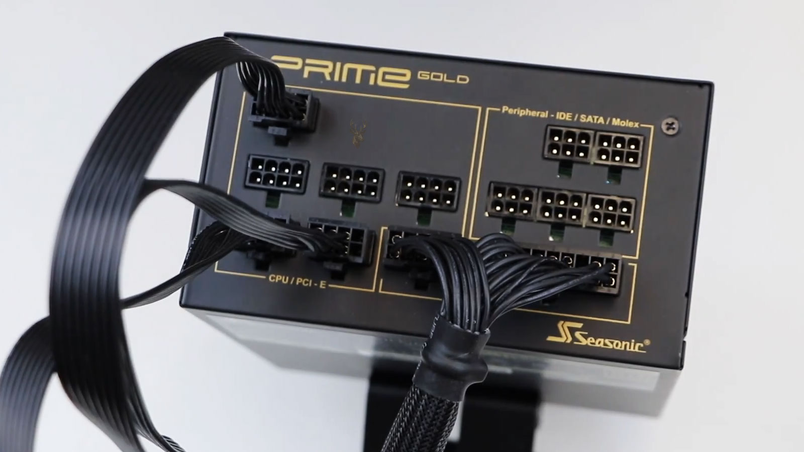
Traditional ATX power supplies commonly use standardized wire colors to identify major voltage rails and control signals. The Power Good conductor is often gray, while standby power is commonly purple and the power-on control line is often green.
Color should not be treated as the only source of identification. Modular power supplies, custom systems, adapters, proprietary equipment, and sleeved cable assemblies may use different colors or conceal the original wiring.
| Common Wire Identification | Typical Function |
|---|---|
| Gray | Power Good status signal |
| Green | Power-on control signal |
| Purple | Standby voltage |
| Black | Ground |
| Yellow | 12-volt output |
| Red | 5-volt output |
| Orange | 3.3-volt output |
Modular Power Supply Cables Are Not Universally Interchangeable
The motherboard end of an ATX cable may follow a standard connector layout, but the power supply end of a modular cable is not universally standardized. Two cables can physically fit different power supplies while using different internal pin assignments.
Using an incompatible modular cable can place the wrong voltage on a control signal or motherboard power pin. This can prevent Power Good from functioning correctly and may permanently damage connected hardware.
Adapter Cables Can Introduce Additional Failure Points
Adapters are sometimes used when connecting standard power supplies to proprietary motherboards or when converting between connector formats. These adapters must route every voltage, ground, and control signal correctly.
A poorly designed or damaged adapter can introduce resistance, loose contact, incorrect pin assignments, or missing control signals. The computer may receive enough power to illuminate lights while still failing to complete the startup sequence.
Proprietary Computers May Use Different Startup Logic
Many desktop computers follow the general ATX power-control process, but some manufacturers use proprietary connectors, voltage arrangements, signal names, or timing requirements.
Testing these systems with assumptions based only on a standard ATX pinout can produce incorrect conclusions. Service documentation or a verified connector diagram may be necessary before measurements are taken.
Laptop Power Sequencing Is More Complex
Laptops do not normally use the same external ATX Power Good line found in desktop systems. Their motherboards still require controlled power sequencing, but the process is handled through embedded controllers, charging circuits, voltage regulators, enable lines, reset signals, and several internal status outputs.
A laptop may begin with adapter detection and standby rails before enabling memory, processor, graphics, and display power. Failure at any stage can prevent the following stage from becoming active.
Server Power Supplies May Communicate More Detailed Status
Servers often use redundant or hot-swappable power supplies with additional monitoring and communication features. Their status may be reported through dedicated control pins, management controllers, indicator lights, or digital communication buses.
Even in these systems, the underlying requirement remains similar: the motherboard must know that power is available and stable before critical hardware is allowed to operate.
Power Good Can Be Present While the Computer Still Does Not Start
A valid Power Good signal confirms only that the power supply has reported acceptable output conditions. It does not confirm that the motherboard has released reset, that the processor clock is present, or that firmware can be read successfully.
The system may still fail because of damaged processor power circuitry, missing memory voltage, corrupted firmware, a defective clock generator, bent socket pins, or an internal short on another rail.
Power Good is an important checkpoint, but it is not proof that every startup requirement has been satisfied.
A Missing Signal Does Not Always Mean the Power Supply Is Defective
The power supply may withhold or remove Power Good because something connected to it is pulling a voltage rail out of tolerance. A shorted motherboard component, failed graphics card, damaged drive, or incorrect cable can create the condition that prevents the signal from remaining active.
Replacing the power supply without isolating the load may produce the same result and can place the replacement unit at risk.
Disconnecting Nonessential Hardware Can Narrow the Cause
Reducing the computer to its minimum required hardware can help determine whether a peripheral or expansion device is interfering with startup. Storage drives, USB accessories, additional memory modules, expansion cards, and front-panel devices may be disconnected when appropriate.
If the startup sequence becomes stable after one device is removed, the problem may involve that device, its cable, its power connector, or the circuit that supports it.
- Disconnect unnecessary USB devices.
- Remove nonessential expansion cards.
- Test with the minimum supported memory configuration.
- Disconnect secondary storage devices.
- Inspect front-panel ports for bent or shorted contacts.
- Verify that processor and motherboard power cables are fully seated.
A Shorted USB Port Can Affect the Entire Startup Process
Damaged USB ports can contain bent metal contacts that touch the connector shell or another terminal. Because USB power may be available during early startup or standby, a shorted port can overload a rail before POST begins.
The system may respond with immediate shutdown, repeated power cycling, or complete inactivity. Inspecting external ports is therefore part of diagnosing early power failures.
Storage Devices Can Create Startup Power Problems
A failed hard drive, damaged SATA power connector, or shorted storage controller can place excessive demand on the power supply. The computer may behave normally when the device is disconnected and fail again when it is reattached.
This type of failure occurs before the operating system begins loading, so it can be mistaken for a boot-drive or software problem even though the cause is electrical.
Graphics Cards Can Delay or Collapse Startup Power
High-performance graphics cards draw substantial power through the motherboard slot and separate auxiliary connectors. A shorted graphics card, loose connector, damaged adapter, or weak power supply can allow startup to begin before the voltage rails collapse.
The system may shut off immediately, restart repeatedly, or remain powered with no display. Testing with integrated graphics or a known compatible card can help separate graphics power problems from motherboard startup faults.
Processor Voltage Regulator Failure Can Resemble a Power Good Problem
The motherboard voltage regulator module converts the incoming 12-volt supply into the lower voltage required by the processor. If this circuit fails, the main power supply may still assert Power Good while the processor receives no usable core voltage.
Debug lights may stop at the processor stage, fans may continue spinning, and no firmware activity may occur. Diagnosis requires checking the local regulator sequence rather than focusing only on the main power supply.
Memory Power Must Also Stabilize Before Initialization
Memory modules rely on motherboard-generated voltages and control signals. If the memory rail is missing, delayed, or unstable, the processor may begin firmware execution but fail during memory initialization.
This can produce repeated restart cycles that appear similar to an unstable Power Good signal. Motherboard debug indicators, diagnostic codes, and voltage measurements can help distinguish between these stages.
Firmware Can Intentionally Restart the System During Training
Some modern motherboards restart several times while training memory, applying new processor settings, or recovering from firmware changes. These controlled restarts do not necessarily indicate a failed power supply.
The pattern should be compared with the motherboard documentation and the recent history of the computer. Continuous cycling that never reaches POST is different from a limited number of expected training restarts.
Cold Starts and Warm Restarts Can Behave Differently
A cold start begins after the computer has been fully powered down, while a warm restart occurs without completely removing all operating power. Different circuits and timing conditions may be involved in each process.
A system that fails only after being disconnected from electricity may have trouble establishing standby power, charging internal capacitors, or completing the initial power sequence. A system that fails only during restart may involve firmware, reset logic, or a device that does not reinitialize correctly.
Temperature Can Change Startup Reliability
Aging capacitors, cracked solder joints, weak semiconductor components, and marginal connector contact can behave differently when cold or warm. A computer may fail during the first startup of the day and work normally after several attempts.
Other systems start correctly when cold but become unstable after internal temperature rises. Observing the relationship between temperature and the Power Good sequence can help identify intermittent electrical failure.
Aging Capacitors Can Affect Startup Timing
Capacitors help smooth voltage, store energy, and support stable operation inside both the power supply and motherboard. As their electrical characteristics deteriorate, voltage rails may rise more slowly, contain excessive ripple, or drop under load.
The result may be delayed Power Good timing, repeated startup attempts, shutdown under load, or a computer that starts only after being left connected to power for a period of time.
Loose Connections Can Interrupt Control Signals
The main motherboard connector carries both high-current power and low-current control signals. A terminal with weak spring tension, oxidation, heat damage, or incomplete insertion can create intermittent behavior when the case is moved or the cable is touched.
Connector inspection should include both sides of the connection, the individual terminals, cable strain, discoloration, melted plastic, and signs that a pin has moved backward inside the housing.
Heat Damage at the Main Connector Can Become Progressive
Resistance at a poor connection produces heat. As the terminal becomes hotter, oxidation and loss of contact pressure can increase resistance further, creating a cycle of worsening damage.
A computer may initially show occasional resets or startup failures before the connector becomes visibly discolored or melted. Replacing only the power supply may not correct the problem if the motherboard connector has also been damaged.
Power Supply Substitution Must Use a Suitable Replacement
Testing with a known working power supply is a common diagnostic method, but the replacement must provide the correct connectors, sufficient capacity, compatible standards, and proper cable assignments.
An undersized or incompatible unit can create new symptoms and lead to an incorrect diagnosis. Modular cables should remain with the exact power supply model for which they were designed.
Successful Startup With Another Supply Is Strong Evidence
If the computer starts reliably with a verified compatible power supply under the same hardware configuration, the original supply becomes a likely cause. The result is more meaningful when the system is also tested under normal operating load.
One successful startup is not always enough to confirm an intermittent failure. Repeated cold starts, restarts, load testing, and observation over time can provide greater confidence.
Replacing the Power Supply Does Not Repair Motherboard Damage
A defective power supply can expose the motherboard to unstable voltage or repeated shutdown events. Even after the supply is replaced, damaged regulators, connectors, firmware, or components may continue preventing startup.
Diagnosis should therefore confirm that the replacement unit produces stable power and that the motherboard completes the remaining stages of its startup sequence.
Startup Evidence Should Be Evaluated in Order
Effective troubleshooting follows the sequence from incoming power through standby operation, motherboard power request, main voltage activation, Power Good confirmation, local voltage regulation, reset release, firmware execution, POST, and operating-system loading.
Separating these stages prevents a no-display condition from being treated automatically as a graphics problem or a no-boot condition from being mistaken for storage failure. The point where the sequence stops provides the most useful direction for further testing.
Power Good Must Remain Stable After Startup
The Power Good signal is not useful only during the first moment of startup. It must remain in its valid state while the power supply continues delivering acceptable output to the computer.
If voltage conditions deteriorate because of overload, internal failure, excessive heat, or unstable incoming power, the signal may change state and cause the motherboard to reset or shut down the system.
Sudden Resets Can Begin With a Brief Power Disturbance
A computer can restart so quickly that the event appears to be caused by software. In some cases, a brief drop in a voltage rail or Power Good signal interrupts the processor before the operating system can record a complete error.
The user may see the screen go black and the startup logo return without a blue screen, shutdown message, or clear warning. System logs may show only that the previous shutdown was unexpected.
Unexpected Shutdown Records Do Not Identify the Electrical Cause
Operating systems can record that a computer lost power or restarted improperly, but they cannot always determine whether the cause was the power supply, motherboard, wall power, a protection circuit, or manual interruption.
An unexpected shutdown entry confirms that the normal shutdown process did not finish. It should be combined with hardware testing, symptom timing, temperature observations, and load behavior before a conclusion is reached.
A recorded power-loss event describes what the operating system experienced, not necessarily which component caused it.
Heavy Workloads Can Expose Marginal Power Stability
Games, video rendering, processor stress tests, large file transfers, and other demanding tasks can increase current draw rapidly. A power supply that operates normally at idle may become unstable when several components increase their demand at the same time.
If the voltage rails fall outside acceptable conditions, Power Good may be withdrawn and the system may reset or shut down. The failure may appear only during a specific workload, making it seem related to the application rather than the electrical demand it creates.
Transient Loads Can Be More Difficult Than Steady Loads
Modern processors and graphics cards can change power consumption extremely quickly. These rapid changes are known as transient loads and can place different stress on a power supply than a constant electrical demand.
A supply may handle a steady test load but respond poorly when current demand rises abruptly. Weak regulation, inadequate capacity, damaged cables, or aging components can allow a brief voltage drop that interrupts system operation.
Power Supply Capacity Is More Than a Wattage Number
The total wattage printed on a power supply does not describe every aspect of its performance. Output quality, rail capacity, protection design, transient response, temperature rating, connector availability, and internal condition also affect whether it can power a particular computer reliably.
An older high-wattage unit can be less dependable than a properly sized modern supply if its components have deteriorated or its output distribution does not match the demands of the hardware.
| Power Supply Characteristic | Why It Matters |
|---|---|
| Total capacity | Determines the overall load the supply is designed to support |
| 12-volt output capability | Supports processors, graphics cards, motors, and regulators |
| Transient response | Helps maintain stable voltage during rapid demand changes |
| Voltage regulation | Keeps outputs within their intended operating ranges |
| Connector quality | Reduces resistance and overheating at power connections |
| Internal component condition | Affects ripple, timing, efficiency, and long-term stability |
Voltage Ripple Can Affect System Stability
Direct-current output from a switching power supply is not perfectly flat. Small repeating variations known as ripple remain after the conversion and filtering process.
Excessive ripple can stress motherboard regulators, storage devices, graphics cards, and other components even when an average multimeter reading appears normal. An oscilloscope is generally required to evaluate this behavior accurately.
A Normal Average Voltage Can Hide Rapid Instability
A multimeter may show a voltage rail near its expected value while brief spikes, dips, or ripple remain invisible because the display averages the measurement over time.
When a computer has unexplained resets or intermittent startup problems, stable average voltage should not be treated as proof that the power is electrically clean under all conditions.
Power Protection Circuits Can Stop Startup Intentionally
Quality power supplies include protection features designed to react to excessive current, excessive voltage, insufficient voltage, overheating, and short circuits. When one of these conditions is detected, the supply may shut down or refuse to complete startup.
This protective behavior can resemble a defective unit even when the supply is responding correctly to a fault elsewhere in the computer.
- Overcurrent protection reacts to excessive current draw.
- Overvoltage protection responds when an output rises too high.
- Undervoltage protection responds when an output falls too low.
- Short-circuit protection limits damage from direct electrical faults.
- Overtemperature protection shuts the supply down when internal heat becomes unsafe.
Protection Latching Can Require Complete Power Removal
Some power supplies remain shut down after detecting a fault until incoming power is removed. Turning the computer off with the front button may not clear the condition because standby power remains present.
Disconnecting the power cable or switching off the supply for a short period can reset the internal protection logic. If the underlying fault remains, the protection may activate again during the next startup attempt.
A Computer That Starts After Unplugging May Have Several Causes
When a computer starts only after its power cable is removed and reconnected, the behavior may involve a latched protection state, unstable standby power, motherboard control logic, a weak power supply, or a peripheral that did not shut down correctly.
The temporary recovery does not identify the failed component. It shows that completely removing electrical power changed the startup conditions.
Standby Voltage Can Fail While Main Outputs Test Normally
Because standby power supports motherboard control logic before startup, a problem on this rail can prevent the front button from being recognized or cause irregular power-control behavior.
A power supply may produce acceptable main voltages when manually activated yet still fail in normal use because the standby output is missing, weak, noisy, or unstable.
Front-Panel Switch Testing Should Remain Separate
A defective case power switch or damaged front-panel cable can prevent the motherboard from receiving a startup request. This occurs earlier than the Power Good stage because the main power rails may never be requested.
Briefly activating the correct motherboard power-switch pins can help determine whether the case button is involved, but the connector layout must be identified accurately before testing.
Motherboard Power-Control Logic Can Also Fail
The motherboard must detect the power-button input, control the power-on signal, monitor readiness conditions, and coordinate reset release. Failure in this control logic can stop startup even when the power supply itself is capable of producing stable output.
Corrosion, damaged embedded controllers, failed logic components, cracked solder joints, and firmware problems can interrupt this sequence.
The power supply and motherboard cooperate during startup, so either side can interrupt the sequence.
Firmware Settings Can Affect Power Behavior
Firmware controls options such as automatic startup after power loss, wake events, power-button behavior, sleep states, and device initialization. Incorrect or corrupted settings can make the computer appear to power on unexpectedly or respond differently after electrical interruption.
These settings do not generate the Power Good signal, but they influence how the motherboard responds before and after the electrical readiness conditions have been satisfied.
Clearing Firmware Settings Can Change the Startup Sequence
Resetting firmware settings may restore standard memory parameters, processor settings, boot configuration, and power-management behavior. This can help when unstable overclocking or corrupted configuration data prevents normal initialization.
A firmware reset will not repair missing voltage, damaged connectors, failed regulators, or an absent Power Good signal. It is useful only when the electrical foundation of the startup process is already functioning.
Overclocking Can Increase Startup Power Demands
Processor and memory overclocking can increase voltage requirements and make hardware initialization more sensitive to timing and power quality. Settings that operate after the system warms up may still fail during a cold start.
Restoring default settings can help determine whether repeated startup attempts are caused by aggressive configuration rather than a failing power supply or motherboard.
Memory Training Can Temporarily Resemble Power Cycling
When memory settings change, some motherboards perform several controlled startup attempts while testing timing and voltage combinations. Fans may stop and restart, and the system may remain without a display for longer than expected.
Interrupting this process too quickly can prevent successful configuration. Manufacturer documentation can help distinguish expected training behavior from an endless failure cycle.
Debug LEDs Reveal Only the Stage Reached
Motherboard debug lights commonly identify broad areas such as processor, memory, graphics, or boot-device initialization. An illuminated processor light does not necessarily prove that the processor itself is defective.
The board may have stopped at that stage because processor voltage is missing, reset was not released, firmware cannot communicate with the chip, socket contacts are damaged, or an earlier power condition was incomplete.
Diagnostic Code Displays Provide More Detail
Some motherboards include numeric or alphanumeric displays that show initialization codes. These codes can indicate the last routine reached before startup stopped.
The meaning depends on the firmware and motherboard manufacturer. A code should be interpreted with the correct service manual rather than relying on a generic list from an unrelated board.
Beep Codes Depend on Successful Early Initialization
Beep codes can identify certain hardware failures, but the firmware must already be executing and the speaker circuit must be functional. A system that never receives stable power or never releases processor reset may remain silent.
The absence of a beep therefore does not prove that the motherboard is inactive, and it does not isolate the power supply as the cause.
No Display Does Not Always Mean No POST
A computer may complete part or all of POST while failing to produce visible video. Incorrect monitor input, a failed graphics output, damaged cable, unsupported display mode, or graphics initialization problem can hide progress that is occurring internally.
Keyboard light behavior, diagnostic indicators, network activity, storage access, and startup sounds can provide additional evidence about whether firmware execution has begun.
POST Cards Can Monitor Certain Motherboard Activity
Diagnostic POST cards can display firmware codes sent through supported expansion interfaces. They may help determine how far initialization has progressed on compatible systems.
They cannot provide useful codes if the processor never begins executing firmware. A blank or inactive card may indicate an early electrical problem, but compatibility and installation must also be considered.
Thermal Imaging Can Reveal Abnormal Current Draw
A shorted component may heat rapidly when standby or main power is applied. Thermal imaging, controlled current injection, or careful temperature comparison can help locate abnormal power consumption on a motherboard.
These methods require technical judgment because many regulators, processors, and controllers normally warm during operation. Excessive current must be limited to avoid creating additional damage.
Resistance Measurements Can Help Locate Shorted Rails
With power removed, resistance-to-ground measurements can help identify a rail that may be shorted. The result must be interpreted according to the circuit because some low-voltage processor and graphics rails naturally have low resistance.
Comparing readings with board documentation, a known working board, or other similar rails is often more meaningful than using a single universal resistance threshold.
Board-Level Testing Should Follow the Voltage Sequence
Motherboard diagnosis often begins with standby rails and then follows the enable and status signals that activate the remaining regulators. Each voltage may depend on an earlier rail or control condition.
Testing random components without understanding this sequence can overlook the actual cause. A missing downstream voltage may be the expected result of an earlier missing enable signal rather than a failed regulator.
| Diagnostic Stage | Question Being Answered |
|---|---|
| Incoming power | Is suitable electricity reaching the power supply? |
| Standby power | Can the motherboard operate its power-control logic? |
| Power request | Is the motherboard instructing the supply to start? |
| Main outputs | Are the primary voltage rails present and stable? |
| Power Good | Is the supply reporting that those outputs are ready? |
| Local regulators | Are the processor, memory, and chipset voltages being created? |
| Reset and clocks | Can the processor begin executing firmware? |
| POST activity | How far does hardware initialization proceed? |
Replacing Parts Without Sequencing Can Become Expensive
A no-start computer can tempt users to replace the power supply, motherboard, processor, and memory one at a time. This approach may eventually find the fault, but it can also introduce compatibility problems and unnecessary expense.
Testing the startup sequence provides evidence before major parts are replaced. It can also reveal connector damage, shorts, incorrect cables, or assembly errors that would affect replacement hardware in the same way.
Power Supplies Should Not Be Opened for Routine Diagnosis
Internal power supply components connect directly to hazardous incoming voltage. Large capacitors may retain a dangerous charge after the unit is unplugged, and improper probing can cause shock, fire, or equipment damage.
Routine computer diagnosis should use external connector measurements, suitable test equipment, or substitution with a verified compatible unit. Internal power supply repair should be reserved for trained personnel with appropriate safety procedures.
A Paper Clip Test Does Not Confirm Full Operation
Manually activating the power-on control line can show whether a standard power supply starts its fan or produces basic outputs. This is commonly called a paper clip test.
The test does not confirm stable voltage under load, correct Power Good timing, acceptable ripple, proper protection behavior, or compatibility with the motherboard. It should never be treated as a complete power supply diagnosis.
A power supply that turns on outside the computer has demonstrated only that part of its startup circuit responds.
Electrical Ground Reference Is Essential During Testing
Voltage measurements are made relative to a reference point, normally a ground conductor. Poor probe contact or an incorrect reference can produce misleading readings.
The computer should also have proper chassis grounding and intact power connections. Grounding problems can contribute to instability, electrical noise, safety hazards, and inconsistent test results.
Incoming Power Quality Can Affect the Sequence
Low line voltage, repeated interruptions, overloaded circuits, damaged outlets, loose plugs, and failing surge protectors can affect how reliably a power supply starts and operates.
A computer that behaves differently at another outlet or location should be evaluated for external electrical conditions as well as internal hardware problems.
UPS Units Can Introduce Their Own Power Problems
An uninterruptible power supply can protect a computer from short outages, but an aging battery, overloaded inverter, or incompatible output waveform can cause startup or shutdown problems.
Temporarily testing the computer from a verified wall outlet can help determine whether the UPS or surge device is influencing the behavior. This should be done only where the electrical outlet is known to be safe.
Repeated Hard Resets Can Damage Stored Data
When unstable power repeatedly interrupts the computer, files may be left partially written and file system structures may not update correctly. Storage devices can also experience additional stress during repeated startup attempts.
Important data should be backed up as soon as the computer becomes stable enough to access. Continued use should not be treated as harmless simply because the machine eventually starts.
Intermittent Power Problems Often Become More Frequent
A weak connector, aging capacitor, cracked solder joint, or deteriorating semiconductor may initially fail only under specific temperature or load conditions. As the damage progresses, startup attempts may become less successful and operating periods may become shorter.
Early diagnosis can reduce the risk of secondary damage and provide more opportunities to secure important files before the computer stops working completely.
Successful Repair Requires More Than Reaching the Desktop
A computer that starts once after a repair has not necessarily been proven reliable. The system should complete repeated cold starts and restarts, remain stable under load, and show no unusual connector heating or voltage behavior.
Testing should reflect the conditions that previously caused the failure, including heavy graphics use, processor demand, attached devices, and normal operating temperature.
Power Good Helps Separate Electrical Startup From Software Booting
The Power Good signal operates before Windows, macOS, Linux, or any other operating system begins loading. A failure at this stage cannot be corrected by reinstalling software, repairing boot files, or replacing the storage drive.
Recognizing this distinction prevents electrical no-start conditions from being confused with operating-system boot failures that occur after POST has already completed.
A Small Signal Controls an Important Transition
The Power Good line carries very little current, yet it plays an important role in coordinating the transition from unstable electrical startup to controlled processor operation. It allows the motherboard to wait until the power supply reports that its primary outputs are ready.
When the signal is missing, delayed, unstable, or withdrawn, the computer may fail before firmware begins, restart repeatedly, or shut down without a clear software error. Similar symptoms can also result from motherboard regulators, shorted devices, incorrect cables, damaged connectors, or failed control logic.
Accurate diagnosis follows the startup sequence instead of relying only on spinning fans, illuminated lights, or a single voltage reading. Understanding where Power Good fits within that sequence helps reveal how a computer determines when it is electrically safe to begin operating.