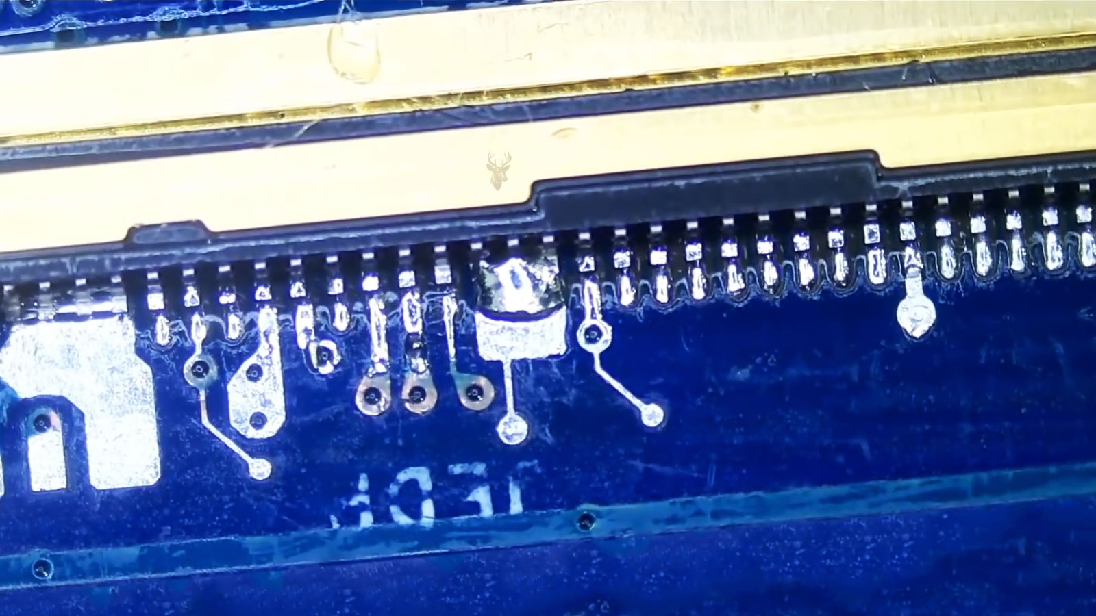
Understanding How Laptop Screens Connect to the System
Every laptop display relies on a small connector that carries power, image data, control signals, and other electrical communication between the motherboard and the display panel. Although these connectors are often hidden behind the bezel or integrated into the rear of the screen, they play a critical role in allowing the display to function correctly.
At first glance, many display connectors appear nearly identical. Their physical size, overall shape, and cable arrangement may seem interchangeable, yet even connectors that look alike can differ significantly in their electrical design, signal assignments, and supported display technologies.
Understanding connector types and pin configurations helps explain why replacing a laptop display often requires more than simply matching the screen size or resolution. The electrical interface between the panel and the computer must also be compatible.
The Connector Is the Display’s Communication Path
The display connector serves as the communication link between the laptop’s graphics hardware and the LCD panel. Through this connection, the system transfers digital image information, supplies electrical power, and exchanges the control signals needed for normal display operation.
Without a properly matched connector and compatible wiring arrangement, the display cannot receive the information required to produce an image, regardless of whether the panel itself is fully functional.
| Signal Type | Purpose |
|---|---|
| Display data | Transfers image information to the LCD panel |
| Power | Supplies operating voltage to display electronics |
| Control signals | Coordinates communication between the system and panel |
| Ground connections | Provide stable electrical reference points |
What Pin Configurations Mean
A pin configuration describes how individual electrical contacts inside a connector are assigned to specific functions. Each contact carries a particular signal, voltage, or ground connection that forms part of the complete communication path between the computer and the display.
The total number of contacts is only one aspect of compatibility. Two connectors may contain the same number of pins while assigning those pins to different electrical functions, making the components incompatible despite their similar appearance.
Connector compatibility depends on both the physical connector and the electrical function assigned to every individual pin.
Physical Similarity Does Not Guarantee Compatibility
Modern laptop displays have become increasingly standardized in appearance, making it easy to assume that similar-looking connectors can be exchanged without issue. In practice, manufacturers often use connectors that resemble one another externally while supporting different communication standards, electrical characteristics, or panel features.
For this reason, technicians typically identify replacement panels using detailed model information rather than relying solely on visual inspection of the connector.
- Connector size alone does not determine compatibility.
- Pin assignments may differ between similar connectors.
- Electrical signaling methods can vary.
- Panel features may require additional communication lines.
- Manufacturer specifications determine proper compatibility.
Different Display Technologies Use Different Interfaces
Over the years, laptop manufacturers have adopted different display interfaces as screen technology evolved. Earlier generations commonly relied on LVDS connections, while many modern systems use Embedded DisplayPort (eDP). Although both technologies transmit display information, they operate differently and are not intended to be interchanged without compatible hardware support.
The connector itself therefore represents only one part of the overall interface. The communication standard used by the laptop and the display panel must also match for normal operation.
Connector Selection Affects Replacement Compatibility
When replacing a laptop display, compatibility depends on a combination of factors that includes the connector style, pin configuration, communication standard, supported panel characteristics, and the system’s display hardware. Matching all of these elements helps ensure that the replacement panel can communicate correctly with the laptop’s internal electronics.
Common Laptop Display Connector Formats
Laptop display connectors are commonly identified by their pin count, physical width, contact arrangement, and interface type. Some configurations appear more frequently than others, but the exact connector used depends on the laptop generation, display resolution, refresh rate, panel features, and internal design.
Thirty-pin and forty-pin connectors are widely associated with modern laptop displays, although the number of pins alone does not confirm which panel will work. The same pin count may support different resolutions, backlight arrangements, touchscreen functions, or signal configurations.
| Connector Format | Typical Use | Important Consideration |
|---|---|---|
| 30-pin eDP | Common in many standard modern laptop displays | Resolution and panel specifications must still match |
| 40-pin eDP | Often used for higher-resolution, high-refresh-rate, or touchscreen panels | Different 40-pin arrangements may not be interchangeable |
| 40-pin LVDS | Found in many older laptop display assemblies | It is not electrically compatible with a 40-pin eDP panel |
The Difference Between LVDS and eDP
Low-Voltage Differential Signaling, commonly called LVDS, was widely used in earlier laptop display systems. It transmits image data across multiple electrical channels and was suitable for the resolutions and display designs common during its period of widespread use.
Embedded DisplayPort, or eDP, became more common as laptop displays required higher resolutions, improved power management, thinner cable assemblies, and support for newer panel technologies. It uses a different communication method and can deliver greater bandwidth with fewer signal lanes.
Because LVDS and eDP use different signaling standards, a panel designed for one interface cannot normally replace a panel designed for the other. Even when the connectors appear similar or contain the same number of pins, the motherboard, cable, and display must all support the same interface.
Why Some 40-Pin Connectors Are Different
The term 40-pin connector can describe several display arrangements that are physically similar but electrically different. One version may be designed for an older LVDS panel, while another may support an eDP touchscreen or a high-refresh-rate gaming display.
Some forty-pin eDP connectors include additional contacts for touchscreen communication. Others use the extra contacts to support increased display bandwidth, additional data lanes, or panel-specific functions. A connector that fits into the socket may therefore still be unsuitable for the display.
- A 40-pin LVDS connector is not the same as a 40-pin eDP connector.
- A touchscreen panel may use a different pin arrangement from a non-touch panel.
- High-refresh-rate displays may require more signal bandwidth.
- Higher-resolution panels may need a different cable or lane configuration.
- Connector position and mounting orientation can also vary.
Display Resolution Can Affect Connector Requirements
Resolution determines how much image information must travel from the graphics system to the display. A basic panel with a lower resolution may require less communication bandwidth than a high-resolution screen that must update significantly more pixels during every frame.
For this reason, replacing a standard display with a higher-resolution version may require more than finding a panel with the same physical dimensions. The display cable, connector pinout, motherboard output, and firmware support must be capable of handling the upgraded panel.
A replacement screen can have the correct size and connector shape while still requiring more display bandwidth than the laptop was designed to provide.
Refresh Rate Creates Additional Compatibility Requirements
A display’s refresh rate indicates how many times the panel can update its image each second. Standard laptop panels commonly operate at lower refresh rates, while gaming laptops may use displays capable of much faster updates.
Higher refresh rates increase the amount of data that must be transmitted through the display connection. The cable and connector configuration must provide enough signal capacity to support the panel at its intended resolution and refresh rate.
Installing a high-refresh-rate panel into a laptop originally designed for a standard display may result in no image, reduced performance, visual instability, or operation at only a limited refresh rate. Compatibility must be confirmed across the complete display path rather than assumed from the panel dimensions.
Touchscreen Panels May Combine Multiple Functions
Some laptop display assemblies combine image transmission and touchscreen communication within the same connector area. Other designs use a separate cable for the touch digitizer. This difference affects both the connector pinout and the number of cables routed through the hinge assembly.
A touchscreen display may therefore have the same outer dimensions as a non-touchscreen panel while requiring a different connector, cable, mounting arrangement, or bezel. The presence of additional contacts does not automatically mean the panel supports every touchscreen system.
Connector Location and Orientation Also Matter
Display connectors can be positioned along different areas of the panel, including the lower left, lower right, or center. The cable installed in the laptop is routed to reach a specific location without being stretched, folded sharply, or placed under pressure.
A replacement panel with the correct electrical specifications may still be unsuitable when its connector is located in a different position. Attempting to force the existing cable to reach can damage the cable, loosen the connector, or place excessive strain near the display hinge.
| Physical Detail | Possible Compatibility Problem |
|---|---|
| Connector location | The installed cable may not reach the panel socket safely |
| Connector orientation | The cable contacts may face the wrong direction |
| Panel thickness | The screen may not fit correctly inside the display housing |
| Mounting tabs | Screw locations may not align with the laptop lid |
| Cable routing | The connector may be placed under stress near the hinge |
The Display Cable Must Match the Panel
The internal display cable is designed around the motherboard output and the specific panel configuration installed in the laptop. It carries the required data lanes, power connections, control signals, and any additional communication lines used by the display assembly.
Changing the panel without confirming cable compatibility can create problems even when the connector can be inserted physically. A different cable may be required when changing resolution, refresh rate, touchscreen capability, or display interface.
Connector Locks Help Maintain Stable Contact
Laptop display connectors frequently use adhesive strips, metal brackets, locking tabs, or retaining covers to prevent the cable from loosening. These securing methods are important because the display assembly moves every time the laptop lid is opened or closed.
If the connector is not fully seated or properly secured, the laptop may develop intermittent display symptoms. The screen may flicker, lose backlight operation, show distorted colors, or stop displaying an image when the lid is moved.
Incorrect Connections Can Damage Display Components
A laptop display connector carries both low-voltage data signals and electrical power. Connecting an incompatible panel, inserting the cable incorrectly, or working on the connector while power remains present can create a short circuit between contacts that were never intended to interact.
Damage may affect the screen, display cable, motherboard connector, backlight circuit, or other components responsible for producing the image. In some cases, the laptop may continue operating while the internal display remains dark. In more serious situations, the computer may stop powering on until the damaged circuit is diagnosed and repaired.
- Disconnect the charger before working around the display connection.
- Disconnect the internal battery whenever the laptop design permits it.
- Confirm that the connector is aligned before inserting the cable.
- Avoid touching exposed contacts with tools or fingers.
- Never force a connector that does not seat naturally.
Bent and Damaged Pins Can Change Display Behavior
The contacts inside a laptop display connector are extremely small and closely spaced. A single bent, recessed, contaminated, or damaged contact can interrupt one part of the communication path while leaving the remaining connections intact.
This is why connector damage does not always produce a completely blank screen. Different contacts are responsible for power, data lanes, identification signals, backlight control, and grounding. The symptoms depend on which part of the connection has been affected.
| Possible Connector Problem | Potential Display Symptom |
|---|---|
| Interrupted data contact | Lines, flickering, distortion, or an unstable image |
| Backlight control failure | A faint image that is visible only under strong light |
| Power contact damage | No image or no panel operation |
| Loose ground contact | Intermittent behavior or visual instability |
| Identification signal problem | Incorrect detection or failure to initialize the panel |
Contamination Can Prevent Reliable Electrical Contact
Dust, adhesive residue, corrosion, and liquid contamination can interfere with the small contacts inside a display connector. Even when the cable appears fully inserted, contamination may prevent one or more pins from making a stable electrical connection.
Liquid exposure is especially concerning because corrosion may continue developing after the laptop has dried. A display problem that first appears intermittent can become permanent as contact surfaces and nearby circuit traces deteriorate.
A connector can look properly seated while damaged or contaminated contacts prevent reliable communication with the display.
Panel Model Numbers Provide More Reliable Identification
The model number printed on the rear label of the original display panel is one of the most useful references when identifying a replacement. It can reveal the manufacturer, screen size, resolution, connector type, interface, panel technology, and other specifications needed for comparison.
However, replacement decisions should not depend on a single specification. Manufacturers may produce several panel revisions with similar model numbers, and compatible alternatives may use different numbering systems. The complete set of electrical and physical characteristics must be evaluated together.
Laptop Model Numbers Alone May Not Identify the Installed Screen
A single laptop model may have been sold with several display options. Depending on its original configuration, the same product family might include standard-resolution, high-resolution, touchscreen, high-refresh-rate, or different panel technology choices.
Two laptops with the same exterior design may therefore contain different display cables and panel connectors. Identifying the exact screen already installed is often more reliable than assuming that every configuration within the laptop series uses the same component.
Display Upgrades Require Complete Compatibility
Some laptop owners consider upgrading to a brighter panel, higher resolution, faster refresh rate, or improved color range when replacing a damaged screen. These upgrades may be possible in certain systems, but they depend on more than the physical size of the display.
The motherboard must provide the correct interface and sufficient display bandwidth. The internal cable must contain the required data lanes and pin assignments. The replacement panel must fit the lid, align with the mounting points, and operate within the electrical limits supported by the laptop.
- Panel dimensions and thickness must fit the display housing.
- The connector type and pinout must match the cable.
- The interface must be supported by the motherboard.
- The cable must support the required resolution and refresh rate.
- Mounting points and connector position must align correctly.
- Touchscreen and backlight functions must be supported when required.
Symptoms Should Be Diagnosed Before Replacing the Panel
A blank, flickering, distorted, or intermittent laptop display does not automatically mean that the LCD panel has failed. Similar symptoms can result from a damaged display cable, loose connector, motherboard circuit problem, graphics failure, backlight issue, or incorrect software configuration.
Testing the laptop with an external monitor can help determine whether the computer is still generating an image, but this test does not identify every internal display problem. The internal panel follows a separate connection path and may fail even when an external display operates normally.
Careful Inspection Helps Prevent Unnecessary Replacements
Before a replacement panel is ordered, the original screen, cable, connector, and laptop configuration should be examined carefully. Confirming the panel model, connector location, interface type, pin count, mounting arrangement, resolution, and additional features reduces the risk of selecting an incompatible component.
This inspection is especially important when the laptop has already been repaired, modified, or fitted with a replacement screen in the past. The panel currently installed may not match the component originally listed for the laptop model.
Proper Connector Matching Protects the Entire Display System
Laptop display panel connectors may be small, but they carry every signal required for the screen to operate. Their pin assignments determine how image data, electrical power, backlight control, identification information, and other functions travel between the motherboard and the panel.
Matching only the screen size or pin count is not enough. Reliable replacement requires the correct interface, connector arrangement, cable support, display specifications, physical fit, and mounting configuration. Careful identification prevents incompatible installations, reduces the risk of electrical damage, and helps ensure that the complete display system operates as intended.