Switch Port Indicators Can Reveal Network Problems Quickly
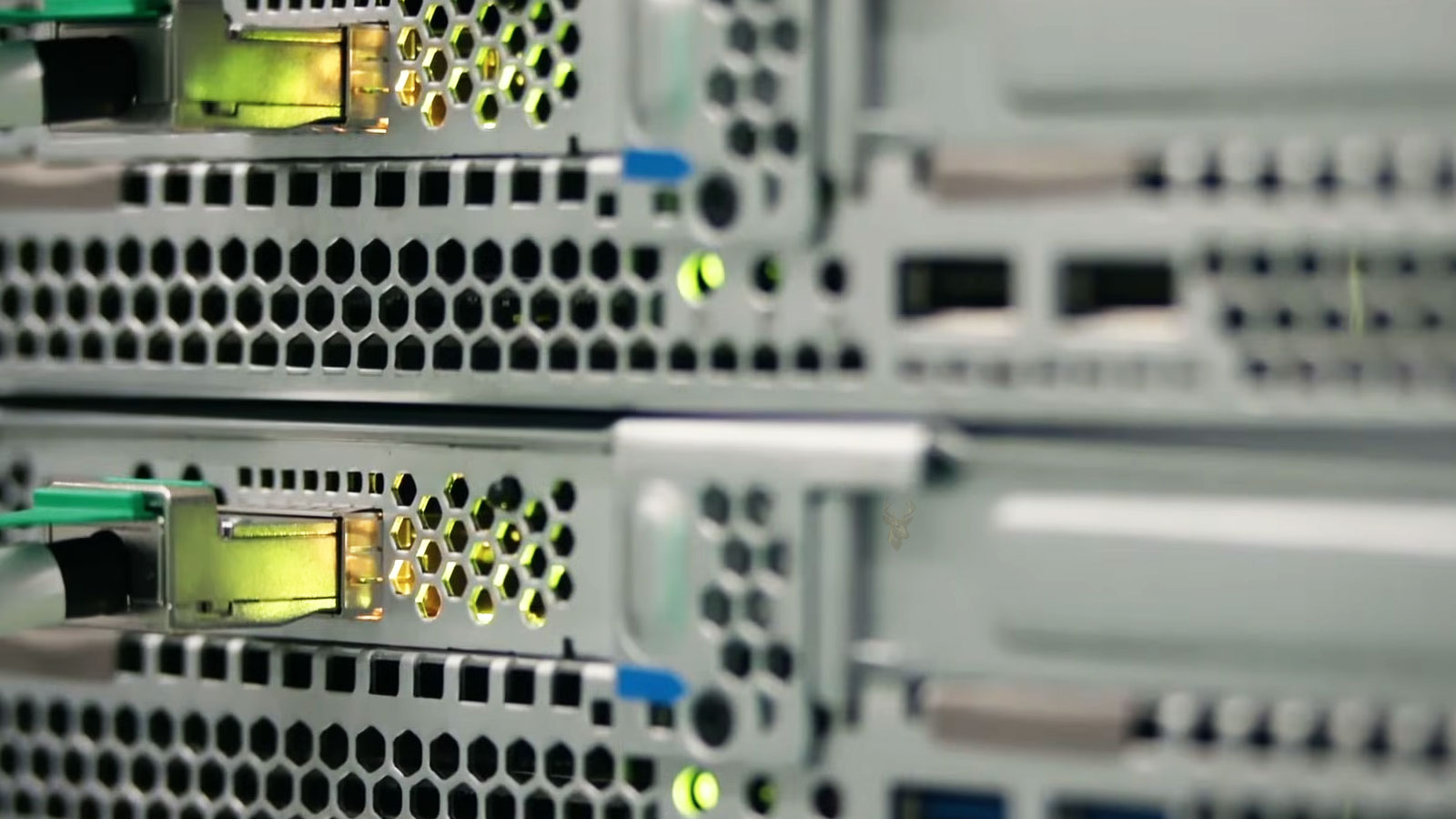
Most business network switches include small LED indicators beside each Ethernet port. Although they are easy to overlook, these lights provide valuable information about the condition of a network connection before any software diagnostics or testing tools are used.
A quick look at the port LEDs can often determine whether a device is physically connected, whether communication is taking place, and, on many switches, the speed at which the connection has been established. This information helps narrow the source of a network problem before cables, computers, or configuration settings are examined in greater detail.
Different switch manufacturers use different colors, blinking patterns, and combinations of LEDs, but the general purpose remains the same. The indicators provide a visual summary of what the switch detects at each network port.
A network switch can often reveal the status of a connection before a computer reports any network error.
Understanding these indicators helps separate physical connection problems from higher-level network issues. If the switch never detects a link, software troubleshooting inside the operating system is unlikely to resolve the problem until the physical connection has been restored.
A Link Light Indicates Basic Communication
The first function of a switch port LED is to indicate whether an Ethernet link has been successfully established between the switch and the connected device. Before computers exchange files, access shared folders, or browse the internet, both ends of the connection must recognize each other electrically.
If the link light remains off, the switch has not detected a valid network connection. This may result from a disconnected cable, damaged connector, powered-off device, failed network adapter, incompatible equipment, or a fault somewhere along the physical network path.
When the link light illuminates steadily, the switch has successfully established communication with the connected device. This does not necessarily guarantee that the network is functioning correctly, but it confirms that the physical Ethernet connection is active.
For this reason, network troubleshooting often begins by observing the switch rather than immediately opening diagnostic utilities on the computer itself.
Blinking Usually Indicates Network Activity
Many switches use a blinking LED to indicate that information is actively moving across the connection. Each flash generally represents network frames being transmitted, received, or both, depending on the switch design.
The blinking pattern often changes throughout the day as network usage increases or decreases. A workstation transferring large files may produce continuous activity, while an idle office computer may blink only occasionally as background communication continues.
The exact blinking speed should not be interpreted as a measurement of network performance. Instead, it simply confirms that the port is actively exchanging information with the connected device.
Activity lights show communication, not network quality.
A rapidly blinking port may simply reflect heavy network traffic, while a slow blinking port may belong to a computer that is currently idle but still communicating normally.
By comparing link status with activity indicators, technicians can quickly determine whether a device has no physical connection, an established but inactive connection, or an active network session that is successfully exchanging information.
Although most switch LEDs perform similar functions, the exact colors and blinking patterns vary by manufacturer. Some switches use separate LEDs for link status and activity, while others combine multiple functions into a single indicator that changes color or flashing behavior.
For that reason, the printed labels on the switch or the manufacturer’s documentation should be used to interpret the indicators accurately. Even so, several common behaviors appear across many business networking products.
Many Switches Use Colors to Show Link Speed
On managed and unmanaged business switches alike, different LED colors often represent different negotiated Ethernet speeds. Instead of requiring software to verify the connection, the switch can provide an immediate visual indication of whether the device is operating at 10 Mbps, 100 Mbps, 1 Gbps, 2.5 Gbps, or even higher speeds on supported hardware.
The actual color assignments vary among manufacturers. One switch may use green for Gigabit connections and amber for Fast Ethernet, while another may reverse those colors or use a completely different scheme.
Because of these differences, the color itself is less important than understanding that the switch is displaying negotiated link speed rather than reporting a fault.
An unexpected reduction in negotiated link speed often points toward a physical connection issue rather than a software problem.
A Slower Link Speed Can Indicate a Physical Problem
Modern Ethernet devices automatically negotiate the fastest speed supported by both ends of the connection. If a computer that normally operates at 1 Gbps suddenly negotiates only 100 Mbps, the switch LED may immediately reveal that change before any speed tests are performed.
This reduction may occur because one or more wire pairs inside the Ethernet cable are damaged, a connector has become loose, the cable has been sharply bent, moisture has affected the wiring, or a network adapter has developed a hardware fault.
Although software settings can sometimes influence negotiated speed, unexpected speed reductions frequently begin with a physical issue somewhere along the network connection.
Link speed and link status describe different conditions.
A port may successfully establish a connection while still operating below its expected performance because the hardware negotiated a lower communication speed.
No Link Light Does Not Always Mean the Switch Has Failed
When a switch port shows no link light, it is natural to suspect that the switch itself has failed. In practice, the cause is often located elsewhere in the connection.
A powered-off computer, disabled network adapter, damaged Ethernet cable, loose wall jack, disconnected patch panel, failed network interface card, or inactive docking station can all prevent the switch from detecting a valid Ethernet link.
Checking the physical path from one end of the connection to the other is usually more productive than replacing the switch immediately.
Managed Switches Provide More Than LED Indicators
While LEDs provide immediate visual information, managed switches also record detailed operational data through their management interfaces. Administrators can often review negotiated speeds, error counters, duplex settings, traffic statistics, port utilization, and event logs for each connection.
This additional information helps determine whether a problem involves excessive transmission errors, repeated link interruptions, cable faults, or configuration issues that cannot be identified from the LEDs alone.
| LED Behavior | General Meaning |
|---|---|
| Off | No Ethernet link has been established |
| Solid | A physical network connection is present |
| Blinking | Network traffic is actively passing through the port |
| Different LED color | May indicate a different negotiated connection speed |
| Unexpected speed indication | May suggest a cable, connector, or hardware issue |
By combining LED observations with management information and basic physical inspection, network troubleshooting becomes faster and more systematic. The small indicators beside each switch port often provide the first clues about where the investigation should begin.
Network switch LEDs are most useful when they are interpreted as the beginning of the troubleshooting process rather than the final diagnosis. They can reveal whether a physical link exists, whether traffic is moving, and whether the negotiated speed appears normal, but they cannot explain every network problem by themselves.
A port may display normal link and activity indicators even while the connected computer cannot reach the internet, access a server, obtain an IP address, or communicate with another device. In those situations, the physical connection is working, but the problem exists at a higher level of the network.
Normal LEDs Do Not Guarantee Full Network Access
A solid link light and regular activity confirm that the switch and connected device are exchanging Ethernet frames. They do not confirm that the computer received a correct IP address, reached the proper gateway, resolved domain names, or passed through required firewall and security rules.
This distinction is important because a network problem can exist even when every visible switch indicator appears normal. The LEDs report the state of the physical connection, while access to network resources depends on additional services and configurations.
- Incorrect IP address or subnet settings
- DHCP failure or an expired network lease
- DNS problems that prevent websites or servers from being located
- Firewall rules that block required communication
- VLAN settings that place the device on the wrong network
- Authentication or permission problems affecting shared resources
A working link light confirms connection to the switch, not successful access to every service on the network.
Intermittent Lights Can Point to an Unstable Connection
A port LED that repeatedly turns off and then returns may indicate that the Ethernet link is being lost and renegotiated. This behavior is different from normal activity blinking because the link itself is disappearing rather than simply showing traffic.
Repeated link changes may be caused by a damaged cable, loose connector, failing network adapter, unstable docking station, poor wall jack termination, or a switch port that is no longer maintaining a reliable electrical connection.
On a managed switch, these interruptions may also appear as repeated link-up and link-down events in the port logs. Comparing the LED behavior with the event history can help confirm whether the problem is intermittent rather than a complete failure.
Normal traffic blinking should not turn the link indicator completely off.
If the port repeatedly loses its link state, the physical connection should be inspected before software settings are changed.
A Known-Good Port Helps Isolate the Problem
Moving the Ethernet cable to another available switch port is a simple way to determine whether the original port may be involved. If the connection immediately returns and remains stable on the second port, the first port may require further testing.
This test should be performed carefully in business environments because managed switches may apply different VLANs, security policies, or access settings to individual ports. Moving the cable without checking the configuration can place the device on the wrong network or remove access to required resources.
On an unmanaged switch, the ports generally operate in the same way, making a direct port comparison simpler. Even then, the cable and connected device should also be tested so the diagnosis does not rely on only one change.
Testing With a Second Cable Provides Another Comparison
Replacing the existing Ethernet cable with a known-good cable can help determine whether the problem follows the original cable. This is especially useful when the port LED is off, the link speed has dropped unexpectedly, or the connection repeatedly disappears.
A cable can appear physically intact while containing broken conductors, damaged wire pairs, poor terminations, or internal stress from repeated bending. These defects may allow a connection to work intermittently or only at a lower speed.
When wall jacks and patch panels are involved, replacing only the short patch cable may not test the entire path. The in-wall cabling, keystone jack, and patch-panel termination may also need to be examined.
| Comparison Test | What the Result May Suggest |
|---|---|
| Same device on another switch port | The original port may be faulty or configured differently |
| Known-good cable on the same port | The original cable may be damaged |
| Different device on the same cable | The original network adapter may be involved |
| Direct connection without a wall jack | The structured cabling path may contain the fault |
| Managed switch log review | Repeated link changes or transmission errors may be recorded |
Error Counters Can Reveal Problems the LEDs Cannot Show
A switch port may remain linked while still experiencing communication errors. Managed switches often record counters for failed frames, packet drops, cyclic redundancy check errors, collisions, and other transmission problems.
These counters are useful because the LED may continue to appear normal while the connection performs poorly. A cable with marginal signal quality, electrical interference, or damaged wire pairs may pass some traffic while producing repeated errors and retransmissions.
Increasing error counts should be interpreted in context. A small historical value may not indicate an active problem, while counters that continue rising during testing suggest that the fault is still present.
Power over Ethernet Adds Another Layer of Information
Power over Ethernet switches can provide electrical power and network communication through the same cable. Devices such as wireless access points, internet phones, security cameras, and access-control equipment often depend on this feature.
Some PoE switches include separate indicators for power delivery, while others report PoE status through the management interface. A device may establish a network link but fail to operate correctly if the switch cannot provide enough power or if the port’s PoE function has been disabled.
A switch may also have a total power budget shared among all PoE ports. If that budget is exceeded, newly connected devices may not receive power even though the switch itself remains operational.
Link status and power status are separate conditions.
A PoE device may fail because of inadequate power even when the Ethernet connection appears present.
Port Labels Help Prevent Troubleshooting the Wrong Device
In a small office, multiple cables may connect computers, phones, printers, access points, cameras, and servers to the same switch. Without clear labeling, it can be difficult to determine which port belongs to the device experiencing the problem.
Consistent labels on the switch, patch panel, wall jack, and equipment record reduce confusion and prevent the wrong connection from being disconnected during testing. Managed switches may also allow administrators to assign descriptive names to individual ports.
Accurate labeling becomes especially valuable when a switch is located in a separate equipment room and the affected computer is somewhere else in the building. The technician can match the office location to the correct switch port without tracing every cable manually.
LED Patterns Should Be Compared With Normal Behavior
The most useful comparison is often the way the same port behaved before the problem appeared. A change from Gigabit to 100 Mbps, repeated link interruptions, or a previously active port becoming dark provides more meaningful information than observing an unfamiliar switch without any reference point.
Nearby working ports can also provide context. If several ports lose their indicators at the same time, the problem may involve the switch, its power supply, or an upstream network connection rather than one computer or cable.
If only one port behaves differently while the rest remain stable, the investigation can remain focused on that device and its physical connection.
Switch LEDs Provide Direction, Not a Complete Diagnosis
Port indicators are valuable because they provide immediate information without requiring access to the connected computer. They can confirm link presence, reveal activity, show negotiated speed on supported switches, and expose repeated connection loss.
However, they cannot confirm correct addressing, server availability, internet access, user permissions, or application-level communication. Those conditions require additional testing after the physical connection has been evaluated.
The most effective approach combines LED observations with cable testing, port comparisons, adapter checks, switch logs, and network configuration review. Each step narrows the range of possible causes without replacing components unnecessarily.
Network switch port LEDs are simple indicators, but they can reveal important details about the state of an Ethernet connection. A missing light may point toward a physical break, an unexpected color may reveal a reduced link speed, and repeated loss of the indicator may expose an unstable connection.
When the LEDs appear normal, troubleshooting can move beyond the physical layer to IP addressing, network services, permissions, and other configuration issues. When the indicators are abnormal, the cable, port, adapter, and structured wiring should be examined first.
By using switch LEDs as an early diagnostic reference, small offices can identify connection problems more efficiently and avoid spending time on software changes when the actual fault is located in the physical network path.