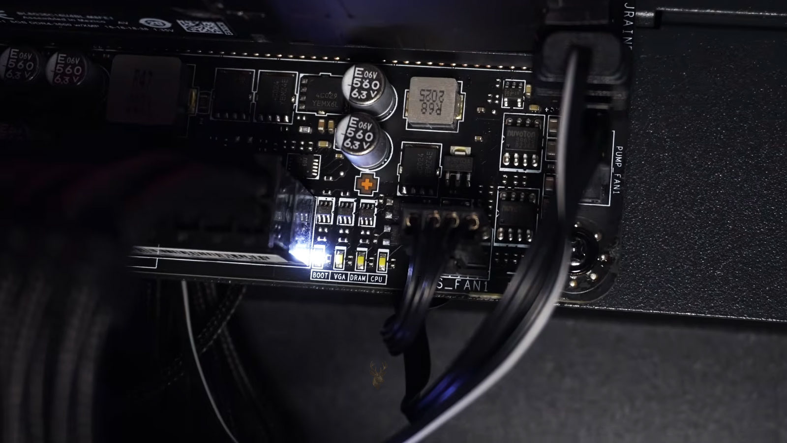
Debug Lights Show Where Startup Stopped
Many desktop motherboards include a small group of diagnostic lights that activate while the computer starts. These lights are commonly labeled CPU, DRAM, VGA, and BOOT. Each label represents a stage of the hardware initialization process rather than a guaranteed diagnosis of one failed component.
During a normal startup, the lights may illuminate briefly and then turn off as the motherboard checks the processor, memory, graphics hardware, and startup drive. A light that remains on can indicate where the process stopped or which device the motherboard could not initialize successfully.
The warning is useful because a computer can receive power, spin its fans, and illuminate its case while still failing before Windows begins loading. The debug light helps separate an early hardware startup problem from an operating-system problem that occurs later.
The Lights Follow the Power-On Self-Test
When the power button is pressed, the motherboard begins a sequence commonly called the power-on self-test. The firmware checks whether essential components can communicate and operate well enough for startup to continue.
The exact sequence differs between motherboard models, but it generally includes processor initialization, memory detection, graphics initialization, and identification of a usable boot device.
| Debug Label | Startup Area Being Checked |
|---|---|
| CPU | Processor detection, power, compatibility, and early firmware initialization |
| DRAM | Memory detection, training, placement, and communication |
| VGA | Graphics card or available display hardware |
| BOOT | Storage device or startup location containing an operating system |
A light may remain on because the named component failed, but it can also stay illuminated when another component prevents that stage from completing. The indicator should therefore direct the next test rather than decide the final repair by itself.
Brief Illumination During Startup Can Be Normal
Users sometimes notice the diagnostic lights only after opening the case or installing a motherboard with visible indicators. Seeing each light activate momentarily does not necessarily mean that the computer has four separate problems.
The motherboard may cycle through the lights as it completes each test. Some systems move through the sequence quickly, while others leave the memory light on longer during training or after hardware changes.
- A light turns on briefly and then moves to the next stage.
- All diagnostic lights switch off before the operating system loads.
- The sequence takes longer after memory or processor changes.
- The computer restarts once while applying new memory settings.
- The BOOT light remains on until a display becomes active and then turns off.
The behavior should be compared with the motherboard documentation because manufacturers do not all use identical timing or indicator logic.
A CPU Light Does Not Always Mean the Processor Failed
A CPU warning light indicates that the motherboard could not complete the processor-related stage of startup. The processor itself may be damaged, but several surrounding conditions can create the same result.
The motherboard must supply correct power, recognize the processor model, communicate through the socket contacts, and load firmware that supports the installed CPU. A failure in any of these areas can leave the CPU light illuminated.
Conditions That Can Produce a CPU Warning
- The processor power connector is unplugged or only partly inserted.
- The motherboard firmware does not support the installed CPU.
- Socket pins or processor contacts are bent, contaminated, or damaged.
- The processor is not seated correctly.
- Excessive cooler pressure has affected socket contact.
- The motherboard voltage circuitry is not supplying stable processor power.
- A short circuit or damaged component prevents early initialization.
Replacing the processor immediately can be expensive and may not correct the problem. Power connections, compatibility, socket condition, installation pressure, and motherboard behavior should be checked first.
Processor Power Is Separate From the Main Motherboard Connector
A desktop motherboard normally uses a large main power connector and a separate processor power connector located near the CPU socket. The computer may still illuminate fans and case lighting when the processor connector is missing.
This can create the appearance that the motherboard has sufficient power even though the processor cannot begin operating. The CPU debug light may remain on, and the computer may produce no display or keyboard response.
| Power Connection | Primary Function |
|---|---|
| Main motherboard connector | Supplies multiple motherboard circuits and expansion functions |
| CPU power connector | Provides power used by the processor voltage-regulation section |
| Graphics card power connectors | Supply additional power required by many dedicated GPUs |
| SATA power connector | Powers storage drives and certain accessories |
The CPU power cable should be identified by its intended purpose. A graphics power connector may appear similar, but modular power-supply cables and connector arrangements are not interchangeable simply because they seem to fit.
Firmware Compatibility Matters After a Processor Upgrade
A motherboard socket can physically accept multiple processor generations while requiring a particular firmware version for newer models. Installing a supported processor before the motherboard firmware is updated can result in a CPU warning and no display.
The computer may be unable to enter the firmware setup because processor initialization never completes. Some motherboards can update firmware without a functioning processor through a dedicated recovery feature, while others require an older supported CPU to perform the update.
- Identify the exact motherboard model and revision.
- Identify the complete processor model.
- Check the manufacturer’s processor support information.
- Confirm the minimum firmware version required.
- Compare it with the version previously installed when known.
- Use only the approved update method for that motherboard.
A processor should not be considered defective solely because the system does not start after an upgrade. Compatibility must be confirmed before replacement decisions are made.
Memory Training Can Keep the DRAM Light On
The DRAM light appears when the motherboard cannot initialize the installed memory successfully. This may happen because a module is loose or defective, but it can also involve memory placement, firmware settings, processor socket contact, or an unstable overclock.
Modern motherboards may perform memory training after new modules are installed, firmware is reset, or memory settings are changed. During training, the computer can remain on the DRAM light longer than expected, restart more than once, or appear inactive before startup continues.
| DRAM Light Behavior | Possible Meaning |
|---|---|
| Turns off after an extended first startup | The motherboard may have completed memory training |
| Remains on indefinitely | Memory detection or initialization did not complete |
| Alternates between CPU and DRAM | Processor-memory communication or training may be repeating |
| Returns only after enabling a memory profile | The selected speed or timing may be unstable |
| Appears after moving the computer | A module may have shifted or a marginal contact may be present |
The amount of time considered normal depends on the platform and memory configuration. Power should not be interrupted repeatedly during an expected training process unless the system clearly remains stalled beyond a reasonable period.
Memory Placement Must Follow the Motherboard Layout
Motherboards with four memory slots often require a specific pair of slots when only one or two modules are installed. Placing the modules in a different pair may prevent startup or cause the computer to use a less effective memory configuration.
The correct positions are identified in the motherboard manual and may also be printed beside the slots. The required slot for a single module is not always the one closest to the processor.
- Confirm the recommended slot for one memory module.
- Use the recommended paired slots for two modules.
- Open both retaining clips when the slot design permits it.
- Align the module notch before applying pressure.
- Press evenly until the module is fully seated.
- Verify that the contacts are inserted to the same depth on both ends.
A module can appear installed while one end remains slightly raised. The system may then stop at the DRAM light or behave differently whenever the case is moved.
Testing One Memory Module Can Narrow the Failure
When several memory modules are installed, testing one at a time can help identify whether one module or slot prevents startup. Each test should use the motherboard’s recommended single-module slot.
The computer should be fully powered down before memory is removed or installed. Residual power should be allowed to discharge, and static-electricity precautions should be used while handling the modules.
- Disconnect electrical power from the computer.
- Remove all memory modules.
- Inspect the modules and slots for debris or damage.
- Install one module in the recommended test slot.
- Reconnect power and observe the debug sequence.
- Repeat the test with each module individually.
- Test another slot only after the module behavior has been recorded.
If every module fails in one slot but works in another, the problem may involve the motherboard slot, processor socket contact, or memory channel rather than all of the modules.
A VGA Light Points to the Graphics Initialization Stage
The VGA indicator usually means that the motherboard could not initialize an available graphics device. This may involve a dedicated graphics card, integrated processor graphics, the expansion slot, power delivery, or the selected display configuration.
A graphics card can illuminate and spin its fans while still failing to communicate with the motherboard. Lighting confirms that some power is present, but it does not prove that the card is seated correctly or has completed PCIe initialization.
Common Areas to Check When the VGA Light Remains On
- The graphics card is not fully inserted into the motherboard slot.
- An auxiliary graphics power connector is missing or loose.
- The monitor cable is connected to the wrong video output.
- A PCIe riser or vertical mount is interrupting communication.
- The graphics card or motherboard slot is damaged.
- The processor does not include integrated graphics despite motherboard video ports.
- Firmware settings are selecting an unavailable display device.
The graphics card should be supported while it is installed so the case bracket does not pull it partly out of the slot. Heavy cards can tilt when the mounting screws and slot are not aligned correctly.
Motherboard Video Ports Do Not Always Provide Graphics
Video ports on the motherboard depend on graphics capability built into the processor. A motherboard can include HDMI or DisplayPort connectors even when the installed processor model has no integrated graphics hardware.
Connecting the monitor to the motherboard in that situation will not produce an image. The display cable must remain connected to the dedicated graphics card unless a compatible processor with integrated graphics is installed and enabled.
| Display Connection | Requirement |
|---|---|
| Motherboard video output | A processor with supported integrated graphics |
| Dedicated graphics card output | A working GPU, PCIe connection, and required power |
| USB display adapter | Operating-system support and an initialized USB controller |
| Docking station video output | A compatible dock, connection standard, and initialized system |
During an early startup failure, USB adapters and software-dependent display devices may not provide a useful test. A direct motherboard or graphics card output is more appropriate.
A BOOT Light Usually Appears Later in the Sequence
The BOOT light generally means that the processor, memory, and graphics stages completed far enough for the motherboard to search for a startup device. The computer may display the firmware screen but fail to find an operating system.
This can occur when a storage drive is disconnected, the boot order changed, the operating-system loader is damaged, or a newly installed drive has not yet been prepared with an operating system.
- The storage drive is not detected by the firmware.
- The SATA data or power cable is disconnected.
- An M.2 drive is installed in an incompatible or disabled slot.
- The firmware is attempting to start from the wrong device.
- The operating-system boot files are missing or damaged.
- A firmware reset changed the storage or startup configuration.
A BOOT light does not necessarily prevent access to the motherboard firmware. If a firmware screen appears, the installed storage devices and startup order can be reviewed before the operating system is repaired or reinstalled.
The Last Illuminated Light Is Not Always the Failed Part
Debug LEDs divide startup into broad stages, but computer components depend on one another. A processor socket contact problem can prevent a memory channel from working and leave the DRAM light illuminated. A power-supply problem can interrupt graphics initialization and appear as a VGA warning.
The debug light identifies the stage that could not finish. It does not automatically identify the component that must be replaced.
The indicator becomes most useful when it is combined with the recent repair history, component changes, cable checks, minimum-hardware testing, and comparison with known-good parts.
A Changing LED Pattern Can Reveal an Intermittent Condition
A computer does not always stop on the same diagnostic light. One startup may remain on DRAM, another may reach VGA, and a later attempt may continue to BOOT. This changing pattern can indicate an unstable connection, marginal power delivery, inconsistent memory training, or a component that responds differently as temperature and contact pressure change.
The order and timing should be recorded instead of relying on a single attempt. A light that changes after the case is moved, a cable is touched, or the computer cools down provides useful evidence about a physical or electrical problem.
| Changing Pattern | Possible Direction |
|---|---|
| Alternates between CPU and DRAM | Processor socket contact, memory training, or memory-controller communication may be unstable |
| Sometimes reaches VGA and sometimes stops at DRAM | Memory initialization may be marginal rather than completely failed |
| Reaches BOOT only after several attempts | Power, storage detection, or firmware settings may be inconsistent |
| Pattern changes when the case is moved | A loose connection, board flex, or mounting pressure may be involved |
| Pattern changes after the system warms up | Temperature-sensitive hardware or power delivery may be affecting startup |
Intermittent startup should not be considered resolved simply because the computer eventually reaches Windows. A reliable system should complete the same startup sequence consistently.
Clearing Firmware Settings Can Remove an Unstable Configuration
Memory profiles, processor tuning, voltage changes, boot settings, and other firmware adjustments can prevent successful startup. Clearing the stored firmware configuration can return the motherboard to safer default values.
This procedure is commonly called clearing the CMOS or resetting the firmware settings. The correct method varies by motherboard and may use a jumper, dedicated button, removable battery, or manufacturer-specific procedure.
- Record important firmware settings before resetting them when possible.
- Disconnect power before using a motherboard jumper unless the manual states otherwise.
- Use the exact pins or button identified by the manufacturer.
- Allow the first startup additional time for hardware detection and memory training.
- Recheck storage mode, boot order, fan settings, and date after the reset.
A reset can remove an unstable setting, but it can also change storage configuration or startup order. The computer may then show a BOOT light even though the earlier CPU, DRAM, or VGA condition has been corrected.
Memory Profiles Can Cause a DRAM Warning After a Successful Build
Memory modules may start at a conservative default speed and require a firmware profile to reach their advertised performance. Enabling that profile increases speed and may change timing or voltage.
A system can work normally at default settings and stop on the DRAM light after the profile is enabled. This does not automatically mean the memory is defective. The selected speed may exceed what the processor memory controller, motherboard, or complete module set can operate reliably.
| Result | What It May Indicate |
|---|---|
| Starts at default speed but not with the profile | The profile settings may be unstable for the system |
| Works with two modules but not four | The larger memory load may require lower speed or different settings |
| Fails only after a firmware update | Memory training behavior or automatic settings may have changed |
| Restarts repeatedly before showing DRAM | The motherboard may be retrying memory training |
| Profile works after lowering frequency | The original target speed may have been too aggressive |
Stable operation is more important than reaching a marketing speed. Memory settings should be tested under load after the computer completes startup.
Four Memory Modules Can Be Harder to Initialize Than Two
Filling every memory slot places a greater electrical load on the processor’s memory controller. A configuration that works with two modules may fail to train at the same speed after two more are added.
Modules with the same brand and visible specifications are not always identical internally. Kits purchased at different times may use different memory chips or programming, which can make four-module operation less predictable.
- Test the original matched pair by itself.
- Test the additional pair separately.
- Confirm that all modules are installed in the correct slots.
- Return memory settings to default before combining the kits.
- Reduce speed if the full configuration remains unstable.
- Use a complete matched kit when dependable four-module operation is required.
A persistent DRAM light after adding memory should be evaluated as a configuration problem before every module is assumed to have failed.
Processor Socket Contact Can Affect Memory Channels
On many modern platforms, the memory controller is built into the processor. The electrical paths between the processor, socket, and motherboard therefore affect whether each memory channel can operate.
A bent socket pin, contaminated contact, uneven processor seating, or excessive cooler pressure can disable one memory channel and leave the DRAM light on. The memory modules may test correctly in one channel while every slot in another channel fails.
Signs That the Problem May Extend Beyond the Memory Modules
- Every module works in one group of slots but not the other.
- The problem began after removing or reinstalling the processor cooler.
- The motherboard reports less memory than is physically installed.
- Startup changes when cooler mounting pressure is adjusted.
- One memory channel disappears after a processor upgrade.
- Socket inspection reveals bent or uneven contacts.
Processor and socket inspection requires careful handling. Dragging a tool across fine socket contacts can create more damage than the original fault.
Cooler Mounting Pressure Can Distort Contact
A processor cooler must be secure enough to maintain proper thermal contact, but uneven or excessive tightening can flex the motherboard around the socket. On some systems, this can affect processor contact or memory-channel stability.
The problem may begin after a cooler upgrade, thermal-paste replacement, or motherboard reinstallation. The computer can stop on CPU or DRAM even though the processor and memory were working before the service.
- Confirm that the mounting hardware matches the socket.
- Check that spacers and backplates are installed in the correct positions.
- Tighten fasteners gradually in an alternating pattern.
- Avoid forcing one side fully down before the others.
- Verify that the motherboard is not visibly bowed around the socket.
- Retest startup before final cable management is completed.
Loosening the cooler without understanding the mounting design can reduce thermal contact. Any adjustment should preserve even pressure and proper installation.
Case Shorts Can Stop the System at Different Stages
A motherboard can contact the case through an extra standoff, loose screw, damaged wire, or incorrectly positioned metal bracket. This unintended electrical path may prevent startup or cause the diagnostic light to change between attempts.
Case-related shorts are especially important after a new build, motherboard replacement, or major internal service. A standoff left beneath an area without a mounting hole can press against circuitry on the underside of the board.
| Possible Contact Point | How It Can Affect Startup |
|---|---|
| Extra motherboard standoff | May short circuitry beneath the board |
| Loose screw behind the motherboard | Can move and contact different traces |
| Damaged front-panel cable | May short a header or create false button input |
| Misaligned input-output shield tab | Can enter a port or press against a connector |
| Pinched accessory wire | May expose a conductor against the chassis |
Testing the motherboard outside the case can help isolate a chassis-related problem, but it must be placed on a clean, nonconductive surface and handled safely.
Minimum-Hardware Testing Removes Unnecessary Variables
A computer with many drives, expansion cards, USB devices, lighting controllers, and accessories has more possible sources of startup failure. Minimum-hardware testing reduces the system to the components required to reach the firmware screen.
The exact minimum depends on the platform, but it commonly includes the motherboard, processor, cooler, one memory module, power supply, and a usable graphics device.
- Disconnect nonessential storage drives.
- Remove additional PCIe expansion cards.
- Disconnect unnecessary USB and front-panel accessories.
- Use one memory module in the recommended slot.
- Use integrated graphics when the processor supports it.
- Keep only the required power connectors attached.
If the system starts in the reduced configuration, components should be added back one at a time. The LED sequence should be observed after each addition.
Removing Storage Can Help Separate BOOT From Earlier Failures
A motherboard does not normally need an operating-system drive to complete the CPU, DRAM, and VGA stages. Disconnecting storage can clarify whether the computer reaches the point where it searches for a boot device.
If the system consistently reaches a BOOT light with all drives removed, the processor, memory, and graphics stages have progressed farther than they did before. The next investigation can focus on storage detection, boot configuration, or a drive-related electrical problem.
| Result With Storage Disconnected | Possible Interpretation |
|---|---|
| System reaches BOOT consistently | An attached drive, cable, or storage configuration may have affected startup |
| System still stops at CPU | The storage devices were not the primary cause |
| System still stops at DRAM | Memory initialization remains incomplete |
| System reaches firmware setup | Core hardware is operating well enough for further testing |
| System powers off when one drive is reconnected | A power cable, drive, or connector may be shorted |
Storage should be reconnected only while the computer is powered down unless the hardware and procedure are specifically designed for hot connection.
A BOOT Light Can Remain On Even When the Drive Is Detected
The firmware may list a storage device correctly while still finding no usable startup entry. The drive can be electrically connected and visible, but its partition structure, boot files, operating-system mode, or selected startup entry may not match the current firmware configuration.
- The operating system was installed in a different firmware mode.
- The boot entry was removed during a firmware reset.
- The wrong drive is first in the startup order.
- The system partition or boot files are damaged.
- The drive was cloned without the required startup partitions.
- A storage-controller setting changed after service.
Repairing the startup structure should begin only after the correct drive is identified and important data is protected.
Graphics Power Problems Can Leave the VGA Light On
Many dedicated graphics cards require one or more power connectors in addition to the electricity supplied through the motherboard slot. A missing, loose, damaged, or incorrectly connected cable can prevent graphics initialization.
Some cards display their own warning light near the power connector, while others simply leave the motherboard on VGA. Fans or decorative lighting may still operate because partial power is present.
Graphics Power Checks
- Confirm that every required connector is fully inserted.
- Use cables intended for the power supply and graphics card.
- Do not reuse modular cables from a different power-supply model.
- Inspect connectors for heat damage or pushed-back terminals.
- Use separate power cables when the card and manufacturer recommend them.
- Verify that the power supply can support the installed hardware.
A connector that appears seated may still be slightly raised on one side. The retaining clip should align correctly without excessive force.
A Second PCIe Slot Can Provide a Useful Comparison
When the motherboard has another suitable full-length slot, testing the graphics card there can help separate the card from the primary slot. The alternate slot may operate with fewer lanes, but it can still show whether the system completes graphics initialization.
If the card works in the secondary slot but not the primary slot, the primary connector, processor lane connection, socket contact, or motherboard circuitry may require closer inspection.
| Test Result | Likely Direction |
|---|---|
| Card works in both slots | The original failure may have involved seating, settings, or an intermittent connection |
| Card works only in the secondary slot | The primary slot or its lane path may be affected |
| Card fails in every slot | The card, power, firmware, or another system condition may be involved |
| Another card works in the primary slot | The original graphics card becomes more suspect |
| No card works, but integrated graphics does | PCIe graphics initialization or power delivery requires further testing |
The case layout and slot wiring should be checked before assuming that every long connector provides the same electrical capability.
Display Problems After the VGA Light Turns Off May Be Separate
The motherboard can complete graphics initialization and turn off the VGA light while the monitor still shows no image. A bad display cable, incorrect monitor input, unsupported resolution transition, or monitor problem can occur after the diagnostic stage has passed.
The LED state should therefore be observed carefully. If all debug lights turn off, the motherboard may have completed startup even though the display path remains unavailable.
- Verify the monitor is powered on and using the correct input.
- Test another known-good display cable.
- Use another output on the same graphics device.
- Test a different monitor when available.
- Listen for operating-system sounds or observe storage activity.
- Check whether keyboard indicators respond after startup.
A no-display condition should not be treated as a VGA initialization failure when the motherboard’s diagnostic sequence has already completed normally.
Power-Supply Instability Can Mislead the Diagnostic Sequence
The motherboard, processor, memory, and graphics card depend on stable voltage during startup. A weak or failing power supply may allow fans to spin while voltage drops or fluctuates when hardware begins initializing.
The computer may stop on different lights, restart repeatedly, or succeed only after several attempts. These symptoms can resemble separate CPU, DRAM, and VGA problems even though one unstable power source affects all of them.
Fans and lighting prove that some power is present. They do not prove that every voltage remains stable during startup.
A known-good power supply with appropriate capacity and compatible cables can provide a useful comparison. Modular cables should remain paired with the power supply for which they were designed.
Repeated Power Cycling Can Make Diagnosis More Difficult
Turning the system on and off repeatedly may occasionally allow it to start, but it can also interrupt memory training, hide temperature-related behavior, and increase stress on unstable hardware.
Each attempt should have a purpose. The light that remains on, the time it stays illuminated, and any change made before startup should be recorded.
- Make one controlled hardware or setting change.
- Reconnect only the required components.
- Start the system and observe the full LED sequence.
- Allow sufficient time for expected memory training.
- Record the final light and any restart behavior.
- Power down safely before the next physical change.
Structured testing produces more reliable evidence than continuing to press the power button until the computer happens to start.