Stable Processor Operation Depends on Controlled Power Delivery
A computer can start normally, remain usable during light tasks, and then freeze, restart, slow down, or shut off when the processor begins working harder. Although overheating, memory errors, software problems, and a failing power supply can produce similar behavior, the motherboard’s voltage-regulation circuitry can also be responsible.
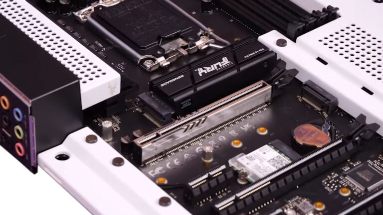
The processor does not use the full voltage delivered by the power supply. Instead, the motherboard converts incoming power into a much lower and carefully controlled voltage appropriate for the processor. This conversion is handled by the voltage regulator module, commonly called the VRM.
When the VRM cannot maintain stable output, the computer may behave normally while demand is low and become unstable as processor activity increases. The symptoms can appear during gaming, video rendering, software installation, file compression, antivirus scanning, or any other workload that raises power consumption.
The Motherboard Converts Power Before It Reaches the Processor
A desktop power supply provides several standard voltage rails to the motherboard and connected hardware. The processor, however, requires a lower voltage that can change rapidly as its workload rises and falls.
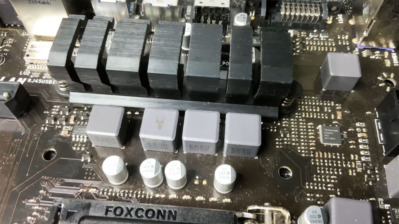
The motherboard’s VRM uses switching components, inductors, capacitors, and a controller to reduce and regulate the incoming voltage. It must respond quickly enough to keep the processor stable while avoiding voltage that is too high, too low, or excessively noisy.
| Power-Delivery Component | General Function |
|---|---|
| VRM controller | Directs voltage changes according to processor demand |
| MOSFETs or power stages | Switch electrical current rapidly during voltage conversion |
| Inductors or chokes | Help smooth and store energy during each switching cycle |
| Capacitors | Reduce voltage fluctuation and supply short bursts of current |
| Heat sinks | Remove heat from voltage-regulation components |
Damage or weakness in any part of this circuit can affect processor stability even when the computer still turns on successfully.
Light Workloads May Not Reveal a Weak Voltage-Regulation Circuit
A computer sitting at the desktop may require relatively little processor power. The VRM can sometimes maintain acceptable voltage under these conditions even when one phase is damaged, a component is overheating, or the motherboard was not designed for sustained high demand.
Opening a demanding program can raise processor activity quickly. Current demand increases, VRM temperature rises, and the voltage-regulation circuit must respond without allowing output to fall outside the processor’s operating range.
- The computer may remain stable during web browsing but restart during gaming.
- Video rendering may fail after several minutes.
- A processor stress test may cause an immediate shutdown.
- Performance may drop sharply after the motherboard becomes warm.
- The system may work with reduced processor settings but fail at normal speed.
This workload-dependent pattern is an important clue, but it does not identify the VRM by itself. Processor temperature, power-supply output, memory stability, and software conditions must also be considered.
Voltage Droop Is Expected Within Controlled Limits
Processor voltage does not remain at one perfectly fixed number. It may change according to frequency, workload, power-saving state, firmware settings, and motherboard design.
A small voltage reduction under load can be intentional. This behavior, often called voltage droop, helps prevent excessive voltage spikes when a heavy workload suddenly ends. Problems begin when the voltage falls farther than the processor can tolerate or fluctuates unpredictably.
| Voltage Behavior | Possible Meaning |
|---|---|
| Small repeatable change under load | May be normal motherboard regulation |
| Large sudden drop followed by a crash | Power delivery may be unable to support demand |
| Voltage remains unusually high | Firmware, sensor, or regulation settings require review |
| Reading changes erratically while idle | Sensor reporting or electrical instability may be present |
| Software value differs from meter testing | The monitoring sensor may not report the exact circuit voltage |
Software voltage readings should be treated as diagnostic clues rather than laboratory measurements. Sensor accuracy varies among motherboards.
VRM Phases Share the Electrical Workload
Many motherboard voltage-regulation systems divide processor power delivery across several phases. Each phase handles part of the electrical load, allowing current to be shared and heat to be distributed among multiple components.
A motherboard advertised with a larger phase count is not automatically better. Component quality, controller design, cooling, current capacity, and the way phases are configured can matter more than the number printed in marketing material.
- The controller activates phases according to processor demand.
- Power stages switch current through the inductors.
- Capacitors smooth the voltage delivered to the processor.
- Additional phases help divide current and heat.
- The circuit adjusts repeatedly as workload changes.
If one phase stops functioning correctly, the remaining phases may carry more load. The computer may continue operating while experiencing higher temperatures and reduced stability.
VRM Heat Can Cause Throttling Before the Processor Overheats
A processor can report an acceptable core temperature while nearby motherboard power components become too hot. Some boards include VRM temperature sensors, but others provide no direct reading to the operating system.
When voltage-regulation components exceed a safe temperature, the motherboard may reduce processor speed, lower power limits, or shut down the computer. This protective behavior can make the system appear slower even though the processor cooler is working properly.
- Processor frequency may drop during a sustained workload.
- Performance may return after the computer cools.
- The system may be stable with the side panel removed.
- A fan directed toward the motherboard may temporarily improve operation.
- Shutdowns may occur sooner during warm room conditions.
Improvement from additional airflow suggests a heat-related condition, but it does not prove whether the affected component is the VRM, chipset, memory, or another area of the motherboard.
Motherboard Heat Sinks Need Airflow to Work Properly
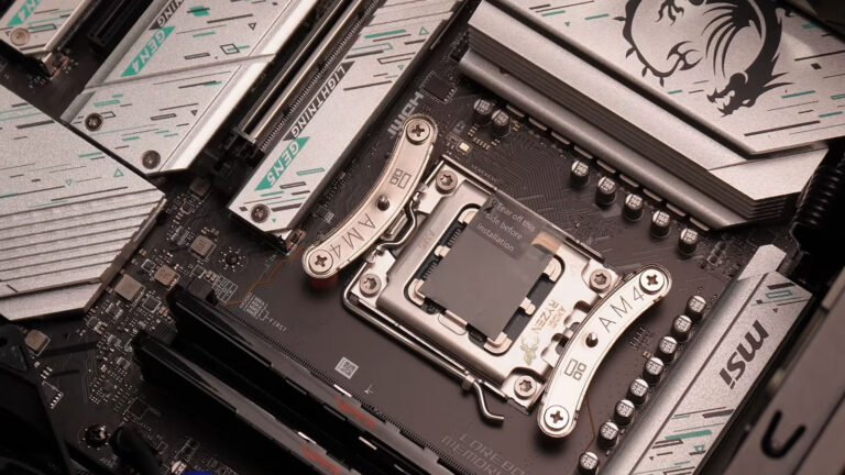
Many motherboards place metal heat sinks over the processor power stages. These heat sinks absorb and spread heat, but they still depend on air moving through the case.
A large liquid-cooling radiator can cool the processor effectively while reducing airflow around the motherboard socket. In some systems, replacing a traditional air cooler with a liquid cooler removes the fan that previously moved air across the VRM heat sinks.
| Cooling Condition | Possible Effect on the VRM |
|---|---|
| Rear exhaust fan missing | Hot air may remain near the processor socket |
| Top radiator exhausts warm air slowly | Heat may accumulate around motherboard components |
| Dust blocks case vents | Reduced airflow raises local temperatures |
| Large cables cover the heat sink | Air movement across the VRM may be restricted |
| Open bench configuration | Natural airflow may differ from normal case operation |
Case airflow should be evaluated as a complete path rather than by counting the number of fans installed.
A Loose Processor Power Connector Can Mimic VRM Failure
The voltage-regulation circuit receives processor power through a dedicated motherboard connector, commonly located near the top edge of the board. Depending on the system, this may be a four-pin, eight-pin, or additional auxiliary connector.
If this plug is not fully seated, has a heat-damaged terminal, or is connected through a defective extension, the VRM may not receive stable incoming power. The result can resemble an internal motherboard fault.
- The locking clip should engage with the motherboard socket.
- The connector should not appear raised on one side.
- No pin should show darkening, melting, or discoloration.
- The cable should not be stretched tightly across the case.
- Only the correct processor power cable should be used.
A graphics-card power connector may look similar but can use a different pin arrangement. Forcing the wrong connector can damage the motherboard or power supply.
Power-Supply Weakness Can Appear Only When Processor Demand Increases
The VRM can regulate power only when the power supply provides a stable input. A weak or overloaded power supply may operate during light use and allow voltage to fall when the processor and graphics card draw more current.
Because both the power supply and motherboard participate in delivering processor power, diagnosis must separate the two. Replacing a motherboard without testing the power supply can leave the original cause unresolved.
- Confirm that the power supply has appropriate capacity.
- Inspect the processor power cable and motherboard socket.
- Test system stability under controlled load.
- Compare behavior with a compatible known-good power supply.
- Continue motherboard diagnosis only after incoming power is verified.
Simple plug-in power-supply testers may confirm that basic voltages are present without reproducing the current demand of a working computer.
Firmware Settings Can Increase Stress on the Power Circuit
Motherboard firmware can change processor voltage, power limits, boost behavior, and current protection. Automatic performance features may allow the processor to consume more power than conservative default specifications.
Manual overclocking, aggressive automatic tuning, or unnecessarily high voltage can increase VRM heat and expose a board that is already operating near its design limit.
- Processor voltage may have been raised manually.
- Automatic enhancement settings may ignore standard power limits.
- Load-line calibration may be configured too aggressively.
- Firmware updates may alter default boost behavior.
- Settings from a previous processor may remain stored.
Loading appropriate firmware defaults can be a useful diagnostic step, but custom storage, fan, boot, and security settings should be documented first.
Processor Compatibility Includes More Than Socket Type
A processor can fit physically into a motherboard socket while still placing more demand on the voltage-regulation circuit than the board can support comfortably. Socket compatibility confirms mechanical and electrical connection, but it does not guarantee that every processor in the same family is appropriate for every motherboard.
Entry-level boards may be designed for lower-power processors, shorter workloads, or conservative firmware limits. Installing a higher-core-count processor can increase sustained current demand even when the system starts and Windows loads normally.
| Compatibility Factor | Reason It Matters |
|---|---|
| Socket type | Determines whether the processor can be installed physically |
| Firmware support | Allows the motherboard to identify and initialize the processor |
| VRM capacity | Determines whether sustained power demand can be supported |
| Cooling design | Controls heat around the processor and power stages |
| Manufacturer support list | Indicates which processors were validated for the board |
A motherboard may technically support a processor while limiting its performance under long workloads to protect the power-delivery components.
High-Core-Count Processors Can Expose Weak Board Design
Processors with more cores can draw significantly more current when many cores operate at the same time. A short burst of activity may not create a problem, but rendering, encoding, compiling, simulation, and stress testing can keep the load elevated long enough for the VRM to overheat.
- The computer may complete brief benchmark runs but fail during longer ones.
- Performance may decline after several minutes of sustained load.
- The motherboard may reduce processor frequency below expected levels.
- VRM heat sinks may become much hotter than nearby components.
- Instability may appear only when all processor cores are active.
This behavior can be mistaken for a defective processor even though the processor operates correctly on a motherboard with stronger power delivery.
Current Limits Can Reduce Performance Without Producing a Crash
Motherboards often monitor current and temperature so they can limit processor power before damage occurs. Instead of shutting down, the system may reduce clock speed, voltage, or boost duration.
The computer remains usable, but demanding programs run more slowly than expected. A user may notice lower benchmark results, inconsistent rendering times, or frame-rate drops during processor-heavy games.
| Observed Behavior | Possible Explanation |
|---|---|
| Clock speed drops while temperature appears normal | Electrical or motherboard power limits may be active |
| Performance improves after cooling the motherboard area | VRM thermal protection may be reducing power |
| Processor reaches full speed only briefly | Short-term boost limits may expire |
| System remains stable at reduced power settings | The original configuration may exceed board capability |
| Performance differs between identical processors | Motherboard firmware and power design may vary |
Reduced performance can therefore be a protective response rather than evidence that the processor itself is defective.
Load-Line Calibration Changes Voltage Behavior Under Demand
Load-line calibration is a firmware setting that influences how much processor voltage decreases under load. It is commonly provided on enthusiast motherboards for tuning and overclocking.
A stronger setting can reduce voltage droop, but an excessively aggressive setting may produce higher voltage spikes when workload changes suddenly. A setting that is too weak may allow voltage to fall far enough to cause calculation errors or crashes.
- Document the current firmware configuration.
- Return manual voltage and calibration settings to appropriate defaults.
- Test stability at stock processor frequency.
- Monitor temperature and voltage trends under controlled load.
- Change only one setting at a time if further tuning is required.
Automatic or highest-level calibration should not be assumed to provide the safest result.
Aging Capacitors Can Reduce Voltage Stability
Capacitors help smooth voltage and supply rapid bursts of current near the processor. Over time, heat and electrical stress can reduce their effectiveness. Older boards may develop instability gradually rather than failing all at once.
Some damaged capacitors develop visible bulging, leaking, or discoloration, while others fail without obvious external signs. Modern solid capacitors are generally durable, but they are not immune to age, manufacturing defects, or prolonged heat exposure.
- The computer may require several startup attempts when cold.
- Crashes may become more frequent as workloads increase.
- Stability may change after the motherboard warms up.
- Voltage readings may fluctuate more than they did previously.
- The system may operate only with reduced processor settings.
Replacing individual motherboard capacitors requires proper tools, component identification, and soldering experience. Installing the wrong type or polarity can damage the board.
Cracked Solder Joints Can Interrupt High-Current Paths
Repeated heating and cooling causes motherboard materials to expand and contract. Over many cycles, solder joints around power stages, inductors, connectors, and other components can weaken or crack.
A marginal joint may conduct during light use and become unstable as current and temperature rise. The computer may then shut down, restart, or recover only after cooling.
| Pattern | Possible Significance |
|---|---|
| Failure appears after warm-up | Thermal expansion may open a weak connection |
| System works again after cooling | The joint may reconnect as materials contract |
| Problem changes when the board flexes | A cracked solder point or trace may be affected |
| One power component appears discolored | Localized heating may have stressed nearby joints |
| Failure remains after power-supply replacement | Motherboard power delivery requires closer evaluation |
Heating the motherboard or pressing on components to reproduce the fault can worsen the damage and should not be used as an informal repair method.
Overclocking Can Hide the Difference Between a Weak Setting and a Weak Board
An overclocked processor requires careful control of frequency, voltage, current, and temperature. Instability may come from an unrealistic processor setting, insufficient cooling, poor silicon tolerance, or a motherboard that cannot sustain the requested load.
Returning the system to verified stock settings is essential before concluding that the motherboard is defective.
- Disable manual frequency multipliers.
- Restore processor voltage to an appropriate automatic or stock value.
- Remove memory overclocking temporarily.
- Disable automatic enhancement features during diagnosis.
- Retest with standard manufacturer power limits.
If the computer becomes stable at stock settings, the previous configuration may have exceeded the capability of the processor, motherboard, cooling system, or power supply.
Memory Errors Can Resemble Processor Power Instability
Memory controllers are commonly integrated into the processor, and some motherboard voltage rails support memory-related functions. Unstable memory settings can therefore produce crashes that appear only during demanding workloads.
A processor stress test may also place pressure on memory and the memory controller, making it difficult to determine which subsystem failed first.
- Disable memory overclocking profiles temporarily.
- Test at the standard supported memory speed.
- Run a dedicated memory diagnostic.
- Test modules individually when errors appear.
- Confirm that memory is installed in the recommended slots.
Stable memory testing helps prevent a motherboard VRM from being blamed for errors caused by aggressive memory timing or voltage.
Graphics Load Can Increase Stress on the Entire Power System
Gaming and rendering often load the processor and graphics card at the same time. This increases total demand on the power supply and raises the temperature inside the case.
A computer that remains stable during a processor-only test but shuts down during combined processor and graphics activity may have a power-supply limitation, inadequate case airflow, or heat buildup around the motherboard.
| Test Result | Diagnostic Direction |
|---|---|
| Fails during processor-only load | Processor cooling, VRM, firmware, or CPU power delivery |
| Fails during graphics-only load | Graphics card, graphics power cable, or power supply |
| Fails only during combined load | Total power capacity or case temperature may be involved |
| Remains stable with reduced graphics power | Power supply or combined thermal load requires review |
| Fails after a consistent warm-up period | Heat-related protection or component weakness is possible |
Combined-load testing should be monitored carefully because it creates substantially more heat than normal desktop use.
Sensor Readings Can Be Incomplete or Misleading
Hardware-monitoring software depends on sensors and motherboard firmware. Some boards report processor voltage, current, and VRM temperature accurately enough for general diagnosis, while others omit values or label them incorrectly.
One unusual reading should not be treated as proof of failure. Results should be compared across firmware monitoring, trusted software tools, observed performance, and controlled hardware testing.
- A missing VRM temperature does not mean the circuit remains cool.
- A fixed voltage reading may indicate limited sensor reporting.
- Brief software spikes may not represent sustained electrical output.
- Different programs may interpret the same sensor differently.
- Firmware updates can change sensor labels or scaling.
Direct electrical measurement should be performed only by someone familiar with motherboard test points and safe procedures.
Visual Inspection Can Reveal Heat and Component Damage
With the computer disconnected from power, the area around the processor socket can be inspected for signs of electrical or thermal damage. The examination should include the processor power connector, power stages, capacitors, inductors, heat sinks, and nearby circuit board surfaces.
- Look for darkened or melted connector plastic.
- Check for cracked, tilted, or missing components.
- Inspect capacitors for swelling or leakage.
- Confirm that VRM heat sinks are mounted securely.
- Look for dust buildup that blocks airflow around the socket.
A board can still have an electrical defect without visible damage, but clear heat marks or burned connectors provide an important reason to stop testing and replace the affected parts.
A Structured Diagnostic Process Prevents Unnecessary Part Replacement
Load-related instability can involve the motherboard, processor, power supply, memory, cooling system, firmware settings, or graphics hardware. Replacing parts without a controlled test sequence can make the diagnosis expensive while leaving the original problem unresolved.
The most reliable approach begins by returning the computer to a known baseline and then testing each major source of instability separately.
- Back up important files before repeated stress testing.
- Load appropriate firmware defaults and remove overclocking.
- Confirm processor and motherboard compatibility.
- Inspect power connectors, cooling components, and visible board damage.
- Test with known-good memory and power delivery when available.
- Apply processor, graphics, and combined workloads separately.
- Record temperatures, frequencies, voltage trends, and failure times.
A repeatable failure under one specific condition provides more useful information than several unrelated crashes during normal use.
Testing at Reduced Processor Power Can Provide an Important Clue
Temporarily lowering processor power limits can reduce current demand and VRM temperature. If the computer becomes stable under the same workload after power is limited, the result suggests that the original configuration was stressing the power-delivery or cooling system.
This does not automatically prove that the motherboard is defective. The processor voltage may have been too high, the power supply may be weak, or airflow may be insufficient. However, the change helps establish that the failure is related to electrical or thermal demand.
| Change During Testing | Possible Interpretation |
|---|---|
| Lower power limit restores stability | The system may be exceeding a thermal or electrical limit |
| Lower clock speed restores stability | Voltage, processor, or motherboard capability requires review |
| Additional motherboard airflow restores stability | VRM or nearby component temperature may be involved |
| Known-good power supply restores stability | The original supply or its cables may be weak |
| No reduced setting improves stability | Memory, motherboard, processor, or software faults remain possible |
Reduced power should be used as a diagnostic comparison rather than a permanent substitute for correcting damaged or inadequate hardware.
Failure Timing Can Separate Immediate Electrical Problems From Heat Buildup
The amount of time between the start of a workload and the failure can reveal useful patterns. A shutdown within seconds may indicate a severe voltage drop, incorrect firmware setting, weak power supply, or immediate protection response.
A failure that develops after ten or twenty minutes is more consistent with accumulating heat, although it can also involve a component whose electrical behavior changes as it warms.
- Immediate restart under load can point toward unstable voltage or power protection.
- Gradual frequency reduction can indicate thermal or current throttling.
- A freeze after a consistent warm-up period may involve heat-sensitive hardware.
- Random failure times can indicate several overlapping problems.
- Stable operation after a long cooling period supports a temperature-related direction.
Recording the exact workload and failure time makes comparisons more reliable after each diagnostic change.
Error Types Can Suggest Which Part of the System Lost Stability
Not every voltage-related failure produces a complete shutdown. The processor may calculate incorrectly, Windows may display a stop error, an application may close, or the system may freeze without losing power.
| Failure Type | Possible Direction |
|---|---|
| Instant power loss | Power supply, motherboard protection, short circuit, or severe voltage failure |
| Immediate restart | Processor instability, reset event, or power interruption |
| Blue-screen error | Processor, memory, driver, or storage instability |
| Application closes during heavy calculation | Calculation errors, memory faults, or software problems |
| Performance drops without a crash | Thermal, current, or firmware power limiting |
The error type should be considered together with temperature, clock speed, and the workload being performed. One symptom alone rarely identifies the failed component conclusively.
Motherboard Firmware Updates Can Correct Power-Management Behavior
Firmware controls processor initialization, voltage requests, boost behavior, current limits, and compatibility with different processor models. An outdated firmware version can mismanage a newer processor or apply settings that were later corrected by the motherboard manufacturer.
An update may improve stability, but firmware installation should not be performed casually on a computer that is already shutting down unpredictably. Losing power during the update can leave the motherboard unable to start.
- Confirm the exact motherboard model and revision.
- Review the update notes for processor or stability changes.
- Use the manufacturer’s supported update method.
- Restore reliable power and stock settings before beginning.
- Do not interrupt the process after firmware writing starts.
After an update, firmware defaults may need to be loaded before custom settings are restored carefully.
Thermal Pads Must Contact the Correct Power Components
Some VRM heat sinks transfer heat through thermal pads placed between the metal heat sink and the power stages. If the pad is missing, torn, incorrectly positioned, or too thin, the heat sink may appear installed correctly while making poor thermal contact.
This condition can appear after motherboard repair, heat-sink removal, or replacement of cosmetic covers near the processor socket.
- The heat sink may remain relatively cool while the power stages overheat.
- Mounting screws may be loose or unevenly tightened.
- A reused pad may no longer compress correctly.
- Protective plastic may have been left on a replacement pad.
- The heat sink may contact only part of the VRM area.
Thermal-pad thickness should match the original design. A pad that is too thick can prevent proper mounting, while one that is too thin may not make contact.
Processor Socket Damage Can Affect Voltage and Signal Delivery
The processor socket carries power, ground, memory, and communication connections between the motherboard and processor. Bent pins, contamination, uneven mounting pressure, or a damaged socket can produce instability that resembles a defective VRM.
Socket problems are especially relevant when the instability began after the processor, cooler, or motherboard was removed and reinstalled.
- The processor may not sit evenly in the socket.
- One or more socket contacts may be bent or contaminated.
- Excessive cooler pressure may distort the board or socket.
- Thermal compound may have entered an exposed contact area.
- The retention mechanism may not be secured correctly.
Socket inspection requires careful lighting and magnification. Attempting to straighten contacts without appropriate tools can cause additional damage.
Replacing Only the Motherboard May Not Correct Heat-Damaged Connections
If a processor power connector has overheated, both the motherboard socket and the cable terminal may be damaged. Installing a new motherboard while reusing a burned connector can create excessive resistance and damage the replacement board.
The same concern applies to modular power-supply sockets, extension cables, and adapters. Every part of a heat-damaged electrical path should be inspected.
A discolored or melted power connection should be treated as damage to the complete connection, not only the most visibly affected side.
Adapters that divide or convert processor power connections should be avoided unless they are specifically approved for the hardware and current requirement.
Professional Board Diagnosis May Require Electrical Measurements
When basic inspection and component substitution do not isolate the problem, diagnosis may require measuring voltage rails, checking resistance, observing switching signals, or using thermal imaging to locate an overheating power stage.
These measurements must be performed while avoiding accidental contact between closely spaced components. A slipped probe can short a live voltage rail and cause immediate board damage.
| Advanced Test | Purpose |
|---|---|
| Voltage measurement | Checks whether a rail remains within the expected range |
| Oscilloscope examination | Reveals ripple, switching behavior, and transient instability |
| Thermal imaging | Identifies components heating abnormally under load |
| Resistance comparison | Helps locate shorted or damaged power paths |
| Component substitution | Separates processor, power supply, and motherboard faults |
Board-level repair may involve replacing power stages, controllers, capacitors, or damaged connectors, but replacement of the complete motherboard is often more practical for standard desktop systems.
A Stable Repair Must Be Verified Under Sustained Load
A computer that starts successfully after a repair has not yet proven that its power-delivery problem is corrected. The system should be tested through sustained processor activity, combined workloads, repeated restarts, and normal everyday use.
- Confirm that firmware settings remain at the intended values.
- Monitor processor and motherboard temperatures during load.
- Verify that clock speed remains consistent without unexpected throttling.
- Check Windows logs for new hardware-related errors or abrupt shutdowns.
- Repeat the workload that originally caused the failure.
The repaired system should remain stable without requiring unusually low power limits, open side panels, or temporary fans directed at the motherboard.
Motherboard Power Delivery Is One Part of a Larger System
Voltage regulation allows a processor to change speed and workload rapidly while receiving controlled electrical power. Weak components, excessive heat, unsuitable firmware settings, damaged connectors, poor airflow, or a processor that exceeds the practical capability of the motherboard can disrupt that process.
Symptoms may include restarts, shutdowns, freezing, blue-screen errors, reduced performance, or stability only at lower processor settings. Because power-supply weakness, memory errors, cooling problems, and processor faults can produce similar results, diagnosis should rely on controlled comparison rather than assumptions.
Verifying compatibility, restoring stock settings, inspecting electrical connections, improving airflow, testing with known-good hardware, and observing behavior under separate workloads can identify whether the motherboard’s voltage-regulation system is operating reliably or requires repair or replacement.