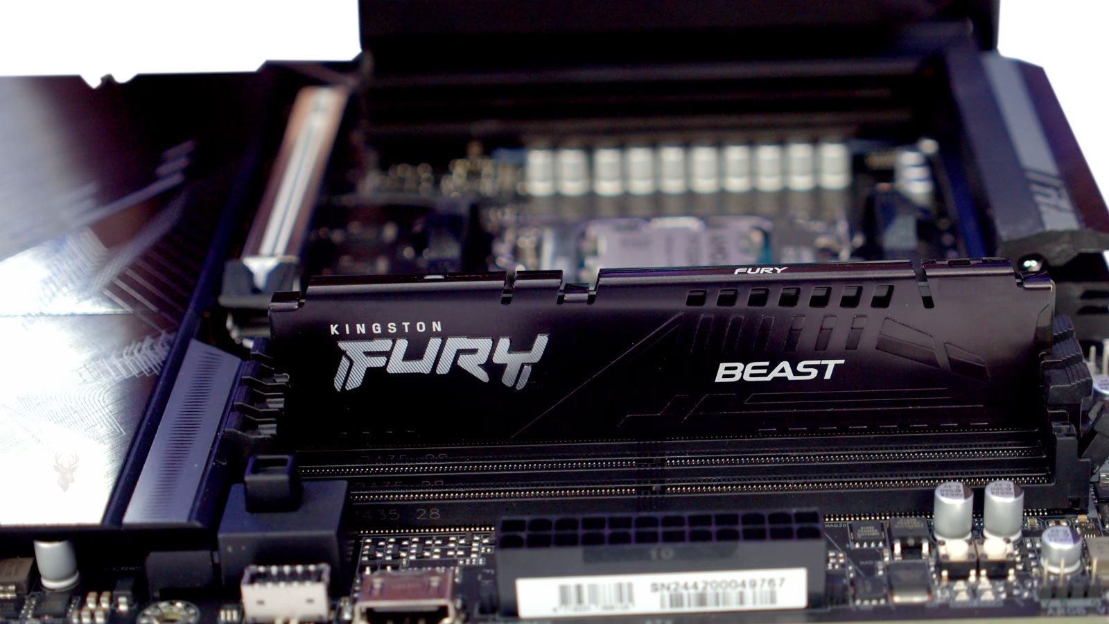
When Moving a Memory Module Changes the Entire Behavior of a Computer
Computer memory problems do not always produce consistent symptoms. A system may fail to start, display a memory warning, freeze during Windows, restart without explanation, or begin working normally after the case is opened and the RAM is removed and reinstalled. The apparent improvement can make the original problem seem resolved even when the underlying contact or slot condition remains.
RAM modules communicate with the processor through hundreds of electrical contacts, motherboard traces, memory slots, and controller connections. Each part of that path must remain electrically reliable. A module that is not fully seated, a contaminated contact, a damaged slot, board flex, or uneven mounting pressure can interrupt only one portion of the memory interface.
These interruptions may change when the computer is moved, warmed, cooled, opened, closed, or reassembled. Removing a module can scrape oxidation from a contact. Pressing it back into the slot can temporarily improve the connection. Tightening a nearby screw can flex the motherboard enough to make the problem better or worse.
Because the symptoms can change after every physical adjustment, intermittent memory contact problems require more than a single successful startup. The system must be tested across different modules, slots, temperatures, and operating conditions before the repair can be considered reliable.
RAM Must Maintain Reliable Contact Across Many Separate Signals
A desktop DIMM or laptop SO-DIMM does not use one simple power and data connection. The edge connector contains many individual contacts for power, ground, addressing, control signals, and multiple channels of data.
If one contact becomes unreliable, the computer may still detect the module while producing errors only when certain memory locations or signaling conditions are used. Another failure may prevent the module from being identified at all.
| Connection Type | General Function | Possible Effect of Poor Contact |
|---|---|---|
| Power contact | Supplies operating voltage to the module | Module instability, failed detection, or startup failure |
| Ground contact | Provides electrical reference and return path | Signal noise, intermittent errors, or unpredictable operation |
| Address signal | Selects memory locations | Specific regions may return incorrect data |
| Data signal | Transfers information to and from memory | Corruption, freezing, application crashes, or memory-test failures |
| Control signal | Coordinates reads, writes, timing, and module selection | The module may not initialize or may operate inconsistently |
| Presence and configuration data | Reports module specifications to the system | Incorrect size, speed, or module information may appear |
The large number of electrical paths explains why a memory problem can affect only one application, one memory range, one startup attempt, or one physical position of the computer.
A Module Can Look Seated While Remaining Slightly Misaligned
Memory slots are designed to hold modules firmly, but a module can appear installed even when one end is not fully inserted. This is particularly common in compact systems where access is limited or nearby cables obstruct the locking clips.
Desktop DIMMs normally enter the slot vertically. Both ends must reach the same depth, and the retaining clips must engage correctly. Laptop SO-DIMMs usually enter at an angle and then rotate downward until side clips hold them in position.
- One retaining clip closes while the opposite side remains slightly raised.
- The module notch aligns correctly, but the contacts do not enter to full depth.
- A cable or heat shield prevents the module from sitting flat.
- The module lifts slightly when another component is installed.
- The slot clips appear closed without applying equal pressure to both ends.
A small seating difference can affect several contacts without being visible from above. The computer may detect reduced memory, fail its startup checks, or operate until vibration or heat changes the connection.
Reseating RAM Can Temporarily Restore a Weak Connection
Removing and reinstalling a memory module changes several physical conditions at once. The edge connector moves across the slot contacts, the retaining pressure is renewed, and minor surface contamination may be displaced.
This can produce an immediate improvement even when the module, slot, or motherboard remains defective. A successful startup after reseating therefore confirms that physical handling affected the problem, but it does not identify which part was responsible.
A computer that starts after RAM is reseated has provided a diagnostic clue, not proof of a permanent repair.
The system should be restarted repeatedly, tested under memory load, and checked after cooling before the connection is considered stable.
Module Contacts Can Develop Surface Contamination
RAM edge contacts are plated to resist corrosion, but they can still collect oils, dust, residue, and environmental contamination. A module handled directly on its contacts may retain skin oils that interfere with reliable contact over time.
Dust inside the slot can also prevent the spring contacts from pressing evenly against the module. In humid or contaminated environments, residue may combine with moisture and create a less reliable electrical path.
| Contaminant or Condition | Possible Source | Potential Effect |
|---|---|---|
| Dust | Cooling airflow and an open computer case | Prevents consistent pressure between slot and module contacts |
| Skin oil | Handling the gold contacts directly | Leaves residue that attracts additional contamination |
| Cleaning residue | Improper liquid or excessive cleaner | Creates a film or traps moisture |
| Corrosion | Humidity, liquid exposure, or contaminated air | Increases electrical resistance or damages contact surfaces |
| Debris | Broken plastic, packaging fibers, or internal fragments | Stops the module from reaching full seating depth |
Visible gold contacts do not guarantee that the hidden contact area inside the slot is clean. Inspection should include the module and the slot whenever access allows it.
Improper Cleaning Can Damage Memory Contacts
Abrasive tools can remove or scratch the protective plating on RAM contacts. Household cleaners may leave conductive or corrosive residue. Excess liquid can enter the slot and remain trapped beneath the connector.
Cleaning should be limited to methods appropriate for electronic contacts. The computer must be disconnected from power, and the module must be handled by its edges.
- Shut down the computer completely.
- Disconnect external power and remove the battery when the design permits it.
- Discharge residual power according to the system’s service procedure.
- Remove the memory module without touching its contact surface unnecessarily.
- Inspect the connector for residue, damage, and uneven wear.
- Use only a small amount of suitable electronics-grade cleaning material when cleaning is required.
- Allow all surfaces to dry completely before reassembly.
An ordinary pencil eraser is sometimes used on exposed contacts, but aggressive rubbing can leave debris and wear the plating. It should not be treated as a universal or risk-free cleaning method.
Compressed Air Must Not Force Debris Deeper Into the Slot
Compressed air can remove loose dust from a memory slot, but the airflow must be controlled. Holding a can incorrectly can release cold liquid propellant, and excessive pressure can move debris into another connector or damage nearby components.
The slot should be inspected with adequate lighting before and after cleaning. Air should not be used as a substitute for identifying corrosion, damaged contacts, or foreign material lodged inside the connector.
- Keep aerosol containers upright.
- Use short, controlled bursts.
- Prevent nearby cooling fans from spinning at excessive speed.
- Do not insert metal tools into the slot.
- Allow any condensation or propellant to evaporate completely.
A connector that remains unreliable after careful cleaning may have mechanical damage rather than ordinary dust contamination.
Memory-Slot Contacts Can Lose Mechanical Tension
The contacts inside a RAM slot are shaped to press against the module when it is installed. If a contact becomes bent, worn, contaminated, or weakened, it may no longer maintain sufficient pressure.
A low-tension contact can work while the module is pressed in one direction and fail when the case is moved. Temperature changes can also alter the small amount of pressure enough to change system behavior.
| Slot Condition | Possible Behavior |
|---|---|
| One contact is bent away from the module | A specific signal may become intermittent or completely open |
| Retaining clip is damaged | The module may lift or move after installation |
| Slot housing is cracked | Contact alignment and seating depth may change |
| Connector solder joint is fractured | Board movement may repeatedly make and break the connection |
| Foreign material is trapped inside | The module may not insert evenly or reach full depth |
A slot with internal contact damage is not repaired simply by installing the module more firmly. Excessive pressure can worsen the connector or flex the motherboard.
Motherboard Flex Can Change Memory Contact
A motherboard is a layered circuit board that bends slightly under mechanical pressure. Installing the board, attaching a heat sink, tightening screws, connecting cables, or closing a chassis can alter its shape.
If a memory-slot solder joint, internal trace, processor socket contact, or board layer is already damaged, small amounts of flex can change whether the electrical path works.
- The computer works while the motherboard is outside the case.
- The problem returns after all mounting screws are tightened.
- Pressing near the memory slot changes startup behavior.
- Installing a large graphics card changes memory stability.
- Moving the computer causes a freeze or failed startup.
These symptoms should not lead to repeated bending or pressing on the board. Intentional flexing can enlarge cracked solder joints and damage internal traces.
Uneven Motherboard Mounting Can Create Intermittent Faults
Desktop motherboards are supported by standoffs positioned beneath approved screw locations. A missing, misplaced, or incorrectly sized standoff can leave the board unsupported or place pressure where it was not designed to receive it.
If one screw is tightened excessively while another area lacks support, the board can remain slightly twisted. The memory slots may then sit under continuous mechanical stress.
| Mounting Problem | Possible Result |
|---|---|
| Extra standoff under the board | Short circuit, board pressure, or trace damage |
| Missing standoff | Excessive flex when modules or cables are installed |
| Overtightened screw | Localized board distortion |
| Uneven chassis surface | Continuous twisting across the motherboard |
| Loose screw | Movement, vibration, or inconsistent grounding |
When memory behavior changes after the motherboard is removed and reinstalled, mounting alignment should be checked along with the RAM itself.
Laptop Base Covers Can Apply Pressure Near Memory Slots
Some laptops place memory modules close to the bottom cover, battery, keyboard, or internal shielding. A warped cover, swollen battery, misplaced foam pad, or incorrectly routed cable can press against the module.
The laptop may work with the cover removed but fail after the screws are installed. In another case, tightening only one corner can shift the chassis enough to alter memory contact.
- The laptop starts with the bottom cover loose but not fully installed.
- The problem changes when pressure is applied to the palm rest.
- A swollen battery pushes against the motherboard or memory shield.
- A screw of the wrong length presses into an internal component.
- An internal cable rests across the SO-DIMM retaining clips.
The cover should not be left loose as a permanent solution. The source of the pressure must be identified so the computer can be assembled without stressing the memory connection.
Processor Socket Problems Can Resemble Defective RAM Slots
On many modern computers, the memory controller is integrated into the processor. Signals travel from the RAM slots through motherboard traces to contacts beneath or around the processor.
A bent processor-socket contact, contaminated pad, uneven cooler pressure, or damaged processor connection can disable one memory channel or produce errors that appear to follow a particular slot.
A memory slot that repeatedly fails does not always mean that the slot connector itself is defective.
The complete signal path includes the module, slot, motherboard traces, socket, processor, and memory controller. Each part must be considered when slot-based testing produces unusual results.
CPU Cooler Pressure Can Affect Memory Channels
A processor cooler must apply sufficient and even pressure for proper thermal contact. Excessive or uneven mounting pressure can distort the motherboard or alter contact between the processor and socket.
After a cooler is removed and reinstalled, a previously working memory channel may disappear, or a failed channel may begin working. This can incorrectly suggest that the RAM module was repaired during reassembly.
| Cooler-Related Condition | Possible Memory Effect |
|---|---|
| One mounting screw is much tighter than the others | Uneven socket pressure may affect signal contact |
| Cooler bracket is misaligned | The motherboard may twist around the processor area |
| Backplate is installed incorrectly | Pressure may be concentrated in the wrong locations |
| Very heavy cooler shifts during transport | Board flex or socket stress may develop |
| Cooler is too loose | Processor temperature may rise and create separate instability |
Cooler mounting should follow the hardware manufacturer’s tightening sequence and pressure specifications rather than being adjusted randomly to influence memory behavior.
One Failed Memory Channel Can Reduce the Detected Capacity
A computer with two installed modules may report only half of the expected memory when one channel does not initialize. The missing capacity may be blamed on a defective module even when both modules work individually.
Testing each module in each supported slot helps determine whether the failure follows the module, remains with the slot, or affects an entire channel.
- Install module A in the primary test slot.
- Confirm whether the system starts and reports the correct capacity.
- Test module B in the same primary slot.
- Install the known-working module in each remaining supported slot.
- Record which slots and combinations start successfully.
- Compare the results with the motherboard’s required population order.
Changing several modules and slots at once makes the results difficult to interpret. One controlled change at a time provides clearer evidence.
Memory Population Order Affects Whether the Computer Starts
Motherboards often require the first module to be installed in a specific slot. On a board with four slots, the preferred first slot may be the second physical connector from the processor rather than the closest one.
Installing memory in an unsupported order can prevent dual-channel operation, reduce performance, or cause startup failure on some systems. The slot labels and motherboard documentation should be checked before a slot is declared defective.
| Installed Modules | General Population Consideration |
|---|---|
| One module | Use the designated primary slot |
| Two modules | Use the paired slots assigned to separate channels |
| Three modules | Support and performance depend on the platform |
| Four modules | All slots are populated, increasing electrical load on the memory controller |
A module that works in the designated primary slot but not in another slot may indicate a slot or channel problem. A module that fails only when placed in an unsupported position may reflect normal platform requirements.
Adding More Modules Increases Electrical and Timing Demands
A computer may operate reliably with one memory module but become unstable when two or four modules are installed. The additional modules increase electrical load and can reduce the timing margin available to the memory controller.
This does not always indicate poor contact. The modules may be incompatible with one another, the selected speed may be too high, or the memory controller may require adjusted settings for a fully populated configuration.
- One module works in every slot, but multiple modules fail together.
- The system starts at a lower memory speed but not at the advertised profile.
- Four modules are unstable while two modules work normally.
- Modules from separate kits have different internal characteristics.
- The motherboard firmware trains memory differently after reassembly.
Contact problems and configuration instability can produce similar symptoms. Testing at standard settings helps separate physical connection issues from aggressive memory timing.
Memory Training Can Make Startup Behavior Change
During startup, many systems perform memory training. The processor and motherboard test timing relationships and select operating values that allow the installed memory to communicate reliably.
After RAM is moved, firmware is reset, or power is disconnected, the computer may restart several times while training. A temporarily black screen does not necessarily mean that the new configuration has failed.
| Training Behavior | Possible Meaning |
|---|---|
| Several automatic restarts after RAM changes | The system may be testing memory settings |
| Long first startup followed by normal operation | Training data may have been stored successfully |
| Repeated training on every startup | The selected settings may be unstable or not being retained |
| Training succeeds only after reseating | Contact, configuration, or module compatibility may be involved |
| Training never completes | Module, slot, controller, or firmware support may be inadequate |
The system should be given sufficient time to complete expected training before power is interrupted. Repeatedly shutting it down during this process can make diagnosis more difficult.
A Firmware Reset Can Hide the Original Memory Configuration
Removing power, clearing CMOS settings, updating firmware, or replacing the battery can return memory settings to automatic defaults. The computer may begin working because an unstable high-speed profile has been disabled.
If this occurs during reassembly, the improvement may be attributed incorrectly to reseating the modules. The actual change may have been a lower memory frequency, relaxed timing, or different voltage selected by the firmware.
- The reported RAM speed is lower after the repair.
- An XMP, EXPO, or similar performance profile is no longer enabled.
- Memory voltage has returned to an automatic value.
- Boot settings and system clock have also reset.
- The computer is stable at default settings but fails when the profile is restored.
Diagnostic notes should include the operating frequency and firmware configuration before and after testing.
Intermittent Contact Can Produce Different Error Codes Each Time
Memory corruption can affect whichever program or system component happens to use the faulty address. The resulting error may change from one failure to the next.
One startup may produce a memory beep code. Another may reach Windows and display a blue-screen error. A later attempt may freeze during a game or damage a file being written to storage.
| Observed Symptom | Possible Relationship to Memory Contact |
|---|---|
| No startup display | Memory initialization may have failed before video output |
| Beep or diagnostic light | Firmware detected missing or unusable memory |
| Random blue-screen messages | Different system data may be corrupted during each failure |
| Application crashes | The affected memory range may be used by one program |
| Damaged files | Incorrect data may be written to storage |
| Freezing under load | Higher memory use may reach unstable addresses |
The absence of one consistent error code does not rule out a memory problem. Intermittent electrical faults often create changing symptoms.
A Successful Memory Test Does Not Always Eliminate Contact Problems
A memory test checks the addresses and patterns available during that session. If the connection is stable at that moment, the test may complete without detecting an error.
The problem may return after the computer warms, cools, moves, or experiences different mechanical pressure. Some faults also appear only at high memory speeds or when several modules are active together.
A passed test confirms that memory worked during the test conditions; it does not prove that an intermittent physical connection can never fail again.
Repeated testing under varied conditions provides stronger evidence than one short diagnostic pass.
Testing One Module at a Time Produces Clearer Results
When several memory modules are installed, a failure can originate from one module, one slot, one channel, or the interaction between multiple modules. Testing the complete set repeatedly may confirm instability without identifying its source.
A controlled test begins with one module in the motherboard’s designated primary slot. Each module is then tested separately in the same slot before a known-working module is moved through the remaining slots.
- Return memory settings to standard automatic values.
- Install one module in the primary slot specified by the manufacturer.
- Confirm startup, detected capacity, and operating speed.
- Run a memory test long enough to exercise the module.
- Repeat the same procedure with each remaining module.
- Use a module that passed testing to evaluate the other slots.
- Record every module-and-slot combination instead of relying on memory.
This process helps determine whether the failure follows one module, remains with one slot, affects a pair of slots, or appears only when the full memory set is installed.
A Fault That Follows the Module Points Toward the RAM
If one module fails in several known-working slots while another module operates correctly in those same slots, the evidence points toward the module itself. The defect may involve a memory chip, the module circuit board, configuration data, or an edge contact.
An intermittent module may pass once and fail later. Testing should therefore include repeated cold starts, warm operation, and sustained memory activity rather than one successful boot.
| Test Result | Likely Direction |
|---|---|
| Module A fails in several slots | Module A is suspect |
| Module B passes in the same slots | The motherboard slots may be functioning normally |
| Module A passes only after reseating | Module contact or intermittent internal failure may be involved |
| Module A fails only at higher speed | Timing, voltage, compatibility, or marginal module quality may be involved |
| Module A reports an incorrect capacity | Module configuration or internal chip failure may be present |
A module should not be declared reliable solely because it works in one slot after being cleaned. The fault must remain absent through repeated testing.
A Fault That Remains With One Slot Points Beyond the Module
If several known-working modules fail in the same slot, the slot or its associated signal path becomes the main concern. The problem may be inside the connector, beneath its solder joints, along the motherboard traces, at the processor socket, or within the memory controller.
A slot that is completely dead may prevent startup whenever it is populated. A partially damaged slot may detect memory but produce errors only under load or after the board warms.
- The system starts with the primary slot but not the secondary slot.
- Every module reports errors in one connector.
- The faulty slot works only when pressure is applied nearby.
- The slot loses contact after the case is closed.
- Two slots belonging to the same channel fail together.
A repeated slot-specific result should lead to inspection of the entire channel path rather than repeated replacement of otherwise functional RAM.
Paired Slot Failures Can Indicate a Memory-Channel Problem
Motherboard slots are grouped into memory channels. On a typical dual-channel desktop board, two slots may belong to channel A and two to channel B. If both slots in one channel fail, the common path between those slots and the processor should be examined.
The shared failure may involve processor-socket contacts, motherboard traces, cooler pressure, firmware settings, or the memory controller inside the processor.
| Pattern | Possible Interpretation |
|---|---|
| One individual slot fails | Local connector or trace damage may be present |
| Both slots in one channel fail | Shared channel path, socket, or controller issue is possible |
| All slots fail with one module | The module is more likely defective |
| All slots fail with every module | Processor, motherboard, firmware, or power problem may be involved |
| Only dual-channel operation fails | Channel synchronization, compatibility, or controller margin may be inadequate |
Channel behavior should be compared with the motherboard documentation because physical slot position does not always make channel grouping obvious.
Cold Starts Can Reveal Contact Problems Hidden During Warm Testing
Electrical resistance, connector pressure, and board dimensions change slightly with temperature. A computer may start normally after running for several minutes yet fail after remaining powered off overnight.
Warm components expand. That expansion may temporarily improve a marginal contact or close a cracked solder joint. Cooling can reopen the fault and cause the next startup to fail.
- The first startup of the day fails, but later attempts work.
- The computer becomes stable after several restarts.
- Memory capacity is missing only when the system is cold.
- Diagnostic lights appear before the system warms.
- Reseating the module restores operation until the next long shutdown.
A repair should therefore be verified after the system has returned to room temperature, not only while it remains warm from testing.
Heat Can Also Cause a Stable Connection to Become Unreliable
The opposite pattern can occur when expansion reduces contact pressure or opens a damaged connection. The computer may start correctly while cold and begin freezing after internal temperatures rise.
Heat-related instability may also result from excessive memory voltage, restricted airflow, failing motherboard regulation, or a processor memory controller operating near its limit.
| Thermal Pattern | Possible Direction |
|---|---|
| Fails only when cold | Marginal contact or cracked connection may close as components warm |
| Fails only when warm | Expansion, voltage instability, or heat-sensitive electronics may be involved |
| Fails under memory load | Temperature, timing margin, or power delivery may become inadequate |
| Works with the case open | Cooling or case pressure may be changing the condition |
| Fails after transport | Mechanical movement may disturb a weak connection |
Temperature patterns are diagnostic clues, but heating or cooling components aggressively can create condensation, thermal shock, or additional damage.
Moving the Computer Can Reproduce a Weak Connection
A desktop that works on a bench may fail after being returned upright, carried to another room, or placed beneath a desk. The movement can shift a heavy graphics card, processor cooler, cable bundle, or loosely retained memory module.
Laptops can respond similarly when the chassis is lifted from one corner or pressure is applied near the memory compartment. Normal handling should not interrupt memory contact, so behavior that changes with movement indicates a mechanical weakness.
- Verify operation in the computer’s normal physical position.
- Check that all memory retaining clips remain fully engaged.
- Support heavy expansion cards and cooling components correctly.
- Confirm that internal cables do not pull against the motherboard.
- Inspect for missing case screws, damaged hinges, or a warped chassis.
The system should not be shaken or struck to reproduce the problem. Ordinary repositioning is sufficient to determine whether normal handling affects reliability.
Transport Can Stress Large Coolers and Motherboards
Large tower coolers and heavy graphics cards place leverage on a motherboard during transport. A computer moved while standing upright can experience forces that do not occur during ordinary desk use.
That stress may slightly shift the processor in its socket, flex the memory-slot area, loosen a module, or worsen an existing solder fracture. The system may arrive with missing memory or no startup display even though it worked before transportation.
A memory failure that appears immediately after transport may be mechanical even when no component looks visibly broken.
After transport, the system should be inspected for cooler movement, board flex, loose modules, displaced cables, and chassis damage before firmware settings are changed.
Diagnostic Lights and Beep Codes Identify the Startup Stage
Many motherboards use status lights, numerical codes, or beep patterns to indicate which part of startup did not complete. A memory indicator means the system stopped during memory initialization, but it does not prove that the RAM module itself is defective.
The same indicator can appear because no usable module is detected, a slot has failed, the processor memory controller cannot communicate, or memory training did not complete.
| Diagnostic Signal | General Interpretation |
|---|---|
| Memory light remains on | Memory initialization did not complete |
| Memory light cycles repeatedly | The board may be retraining or retrying different settings |
| CPU and memory lights alternate | Processor socket, controller, or power initialization may be involved |
| Beep code changes after reseating | The physical memory configuration has affected startup |
| No lights or beeps | Power, board, firmware, or speaker configuration may require evaluation |
The motherboard manual should be used to interpret model-specific codes. Generic beep-code lists can be misleading because manufacturers assign different meanings.
Incorrectly Reported Memory Capacity Is an Important Clue
A computer may start while reporting less RAM than is physically installed. The missing capacity can indicate that one module, one rank, one channel, or one portion of a module failed to initialize.
The amount shown in firmware should be compared with the amount reported by the operating system. A difference can also result from hardware-reserved memory, integrated graphics, or an operating-system limitation, so the location of the discrepancy matters.
- Firmware reports only one of two installed modules.
- The full capacity appears in firmware but not in the operating system.
- Capacity changes after the case is moved.
- The system alternates between two different totals.
- One module is listed with incomplete configuration information.
Capacity that changes between restarts strongly suggests an initialization or connection problem rather than normal memory reservation.
Hardware-Reserved Memory Can Be Mistaken for Missing RAM
Windows may show the installed capacity while marking a portion as hardware reserved. Some reservation is normal for integrated graphics, device mapping, and firmware functions. An unusually large reservation can also occur when a memory channel is not functioning correctly.
If firmware detects the full amount but Windows makes a large portion unavailable, operating-system settings, boot configuration, firmware mapping, or channel problems should be evaluated.
| Observation | Possible Meaning |
|---|---|
| Small reserved amount | Normal device and integrated-graphics allocation may be present |
| Half of installed RAM is reserved | A channel, firmware, or mapping problem may exist |
| Firmware also shows half capacity | The issue occurs before Windows loads |
| Capacity changes after reseating | Physical contact or initialization is likely involved |
| Reserved amount changes with graphics settings | Integrated-graphics allocation may be responsible |
Changing Windows settings cannot restore memory that the firmware never initialized.
Mixed Memory Kits Can Create Intermittent Instability
Two modules may share the same advertised capacity and speed while using different memory chips, ranks, timings, or electrical characteristics. Combining separate kits can therefore create instability even when each module works alone.
The system may operate at standard settings but fail when a performance profile is enabled. It may also train successfully after one reassembly and fail after the next because the timing margin is very small.
- Modules have different part numbers or revision codes.
- One module is single-rank and another is dual-rank.
- The modules require different voltage for their rated speed.
- The firmware selects timings that one module cannot maintain.
- The combined configuration is not listed as validated for the motherboard.
Matched kits reduce compatibility variables, but even a matched kit can develop a defective module or contact problem.
Memory Profiles Can Expose Marginal Hardware
Performance profiles such as XMP or EXPO configure memory above basic standard settings. They can increase frequency, adjust timings, and change voltage automatically.
A connection that operates at a lower data rate may produce errors at a higher rate because there is less timing tolerance. A module can therefore appear repaired after a firmware reset simply because the profile was disabled.
| Configuration | Diagnostic Value |
|---|---|
| Standard automatic settings | Provides a stable baseline for hardware testing |
| Manufacturer memory profile | Tests the rated performance configuration |
| Manual overclock | Adds timing and voltage variables that complicate diagnosis |
| Reduced frequency | Can reveal whether the system lacks margin at higher speed |
| Fully populated slots | Places greater load on the memory controller |
Physical reliability should be established at standard settings before performance profiles are restored.
Automatic Voltage Does Not Always Mean the Same Value
Motherboard firmware may select different voltages after memory training, a BIOS update, or a configuration change. The displayed setting can remain labeled automatic while the applied value changes.
Excessive voltage can increase heat and stress. Insufficient voltage can reduce stability, especially with multiple modules or higher frequencies. Voltage adjustment should not be used to conceal a damaged slot or poor contact.
- Record the actual voltage reported by the firmware.
- Compare it with the memory manufacturer’s specification.
- Return manual overclocking values to normal during diagnosis.
- Avoid large voltage increases intended only to force startup.
- Confirm that motherboard power regulation remains stable under load.
A system that requires unusually high voltage after reassembly may still have a marginal electrical path.
Firmware Compatibility Can Affect Module Detection
Motherboard firmware contains memory-training code and support data for different processors and memory configurations. Older firmware may struggle with newer module designs or high-capacity kits.
A firmware update can improve compatibility, but it can also reset settings and create the appearance that reseating solved the problem. The timing of every change should be documented.
| Firmware Situation | Possible Effect |
|---|---|
| Old firmware with newer RAM | Incorrect detection or failed training may occur |
| Firmware update completed | Compatibility may improve and settings may reset |
| Update interrupted | The motherboard may fail to initialize hardware correctly |
| Settings restored from an old profile | Incompatible timing values may return |
| CMOS battery is weak | Memory settings may not remain consistent between startups |
Firmware should be updated only with stable power and the correct file for the exact motherboard model.
A Weak CMOS Battery Can Change the Testing Baseline
The CMOS battery helps retain firmware settings and the system clock when the computer is disconnected from power. If the battery is weak, memory settings may return to defaults unexpectedly.
A computer that alternates between stable default settings and unstable performance settings may appear to have an intermittent RAM connection when the actual configuration is changing between startups.
- The clock resets after the computer is unplugged.
- Firmware reports that settings were restored to defaults.
- The memory profile disables itself unexpectedly.
- Boot order and fan settings also change.
- Stability differs depending on whether the system remained connected to power.
The battery does not power the RAM while the computer is off, but it can affect which memory settings are used during the next startup.
Memory-Test Errors Must Be Interpreted by Pattern
A memory test may report individual failing addresses, broad ranges of errors, or failures that appear only during specific patterns. The distribution can help distinguish a module defect from a slot, controller, or timing problem.
Errors that follow one module across slots support a module diagnosis. Errors that remain with one slot suggest the signal path. Errors that appear only with multiple modules can indicate channel loading or compatibility.
| Error Pattern | Possible Direction |
|---|---|
| Same module fails in every slot | Defective module or module contact |
| Every module fails in one slot | Slot, trace, socket, or channel problem |
| Errors appear only with all slots populated | Controller load, timing, or compatibility issue |
| Errors appear only after warming | Thermal or marginal electrical behavior |
| Error addresses change randomly | Intermittent connection, timing, or power instability may be present |
The exact address alone rarely identifies the physical chip without detailed module mapping, but the repeatability of the pattern remains useful.
Operating-System Diagnostics Are Useful but Limited
Windows Memory Diagnostic and similar built-in tools can identify some memory errors without requiring separate equipment. They are useful for confirming instability but may not run long enough to reproduce an intermittent contact problem.
A system that crashes before the test loads may require a bootable diagnostic environment. A computer that cannot complete memory initialization may not be able to run software-based testing at all.
- Built-in diagnostics provide an accessible first test.
- Longer external tests can exercise more patterns and passes.
- Software tests cannot inspect connector tension or solder joints.
- A passed test does not verify stability after transport or cooling.
- A failed test confirms corruption but not automatically which component caused it.
Diagnostic software should be combined with controlled physical testing rather than used as the only evidence.
Memory Errors Can Damage Files and Operating-System Data
RAM temporarily holds information before the processor uses it or writes it to storage. If that information changes because of a memory error, corrupted data may be saved to a document, database, program file, or operating-system structure.
Replacing or reseating the RAM stops future errors only if the memory problem was truly corrected. It does not automatically repair files that were already damaged.
- Documents may contain missing or altered content.
- Compressed archives may fail integrity checks.
- Applications may become damaged during installation or updating.
- File-system metadata may be written incorrectly.
- Windows components may require repair after repeated crashes.
Important files should be verified after a period of memory instability, particularly when corruption warnings appeared before the hardware problem was addressed.
Page-File Errors Can Continue After the RAM Is Repaired
Operating systems move some memory contents to a page file or swap area on storage. Corrupted information in RAM can therefore be written to disk and read again later.
After stable memory is confirmed, operating-system checks may still be needed if crashes, damaged applications, or startup errors continue. Persistent symptoms do not always mean the replacement RAM is also defective.
| Continuing Symptom | Possible Cause After RAM Repair |
|---|---|
| Windows still reports damaged files | Earlier memory errors may have corrupted system data |
| One application continues crashing | The program installation or user data may be damaged |
| File-system checks report errors | Incorrect data may have been written before the repair |
| New memory tests pass | The current hardware may be stable even though earlier damage remains |
| Freshly installed software works correctly | Older application files may have been corrupted |
Hardware verification should occur before major software repair so new data is not written through an unstable memory subsystem.
Repeated Crashes Can Corrupt the File System Independently
Unexpected restarts and freezes can interrupt disk writes even when the data in memory was correct. Over time, the storage file system may develop logical inconsistencies that remain after the memory connection is repaired.
A computer may therefore require two separate corrections: one for the intermittent RAM condition and another for the resulting operating-system or file-system damage.
Correcting the hardware fault prevents new corruption, but it does not guarantee that earlier crashes left the stored data untouched.
Backups should be reviewed before repairs are attempted on a file system that contains important data.
Event Logs May Show the Effects Rather Than the Cause
Windows Event Viewer may contain application crashes, unexpected shutdowns, hardware-error reports, or file-system warnings created during memory instability. These records can establish when the failures occurred, but they may not name the faulty module or slot.
Memory corruption can cause many unrelated services to fail. A series of different errors appearing within the same period can be more significant than one isolated event.
- Unexpected shutdown records show that Windows did not close normally.
- Application errors may identify programs affected by corrupted memory.
- Hardware-error events may indicate processor or memory-controller reporting.
- Disk warnings can result from interrupted or incorrect writes.
- Errors that stop after the repair support the hardware diagnosis.
Logs should be compared before and after the physical repair to determine whether the original failure pattern has ended.
Blue-Screen Codes May Change From One Failure to Another
Memory corruption can affect different kernel structures during each session. As a result, the system may display several unrelated stop codes instead of one consistent memory-related message.
A changing collection of blue-screen errors, especially when combined with failed memory tests or changing detected capacity, can support a memory diagnosis.
| Crash Pattern | Diagnostic Significance |
|---|---|
| Same code after the same action | A specific driver or software path may be involved |
| Different codes during unrelated tasks | Memory, power, or broad hardware instability becomes more likely |
| Crashes stop with one module removed | The removed module or multi-module configuration requires evaluation |
| Crashes return after moving the case | Mechanical contact may be involved |
| Crashes continue with known-good RAM | Slot, processor, motherboard, storage, or software damage may remain |
Stop codes should be treated as evidence within the larger testing pattern rather than as a complete diagnosis by themselves.
Application-Specific Failures Can Still Originate in RAM
A memory fault may appear to affect only one game, design program, browser, or database because that application uses more memory or reaches the unstable address range more frequently.
The application may be reinstalled repeatedly without improvement because the installation files become corrupted again or the program continues encountering faulty memory.
- The application crashes only during large projects.
- Small files work while larger files fail.
- The problem appears when several programs are open together.
- Errors occur during decompression, rendering, or compilation.
- The same program works normally after one module is removed.
Memory testing should be considered before concluding that an application is defective when failures increase with memory usage.
Integrated Graphics Can Make Memory Problems Look Like Display Failure
Integrated graphics use a portion of system RAM for video data. An unstable memory region can therefore produce screen artifacts, driver crashes, black screens, or display corruption even when the graphics hardware itself is functioning.
The symptom may change when a discrete graphics card is installed because the system uses memory differently. That change does not automatically prove that the integrated graphics processor is defective.
| Display Symptom | Possible Memory Relationship |
|---|---|
| Artifacts appear only with integrated graphics | Shared system memory may be unstable |
| Black screen occurs before operating-system load | Memory initialization may fail before video output |
| Display driver restarts under load | Corrupted shared-memory data may be involved |
| Discrete graphics reduces the problem | Memory allocation and system load have changed |
| Artifacts remain with known-good RAM | Graphics hardware or motherboard faults require further testing |
Display symptoms should be evaluated alongside memory capacity, diagnostic results, and slot behavior.
Laptop Memory Can Shift When Retaining Clips Are Damaged
Laptop SO-DIMMs rely on small side clips to hold the module flat after it is inserted at an angle. If one clip is bent or broken, the module can rise slightly and lose contact.
A bottom cover or shielding pad may press the module downward temporarily. Once the cover is removed, the module may lift, revealing that the retaining system is no longer functioning correctly.
- One side of the module sits higher than the other.
- The module releases without moving both clips.
- The computer fails when the bottom cover is removed.
- Pressure on the memory compartment changes stability.
- A clip is cracked, loose, or no longer spring-loaded.
Foam, tape, or case pressure should not be used as the primary repair for a damaged retaining mechanism because the contact pressure may remain uneven.
Soldered Memory Changes the Diagnostic Approach
Many thin laptops and modern compact systems use memory chips soldered directly to the motherboard. There is no removable module to reseat, but flex, solder damage, power instability, and memory-controller faults can still produce similar symptoms.
A system with partly soldered and partly removable memory can be tested by removing the replaceable module and evaluating the onboard memory separately.
| Memory Design | Testing Limitation |
|---|---|
| Fully removable RAM | Modules and slots can be isolated individually |
| Partly soldered RAM | Onboard memory remains active during many tests |
| Fully soldered RAM | Board-level diagnosis is required |
| Unified memory architecture | Memory is integrated closely with the processor package |
Replacing a removable module cannot correct errors originating from soldered memory or its motherboard power circuits.
Swollen Batteries Can Distort Laptop Memory Connections
A swollen battery can push against the bottom cover, motherboard, memory shield, or nearby cables. The pressure may bend the board and alter SO-DIMM contact even when the battery does not touch the module directly.
The computer may become more stable with the cover removed because the chassis pressure has changed. Continuing to use a swollen battery is unsafe and can worsen internal damage.
- The trackpad or palm rest rises.
- The bottom cover no longer sits flat.
- Screw holes become difficult to align.
- The memory problem changes when the battery is disconnected.
- Internal shielding or cables show pressure marks.
The battery condition must be corrected before memory stability can be evaluated reliably in the fully assembled laptop.
Wrong-Length Screws Can Press Into the Motherboard
Laptops often use several screw lengths that appear nearly identical. Installing a long screw in a shallow location can press into the motherboard, deform a shield, damage a trace, or create pressure near a memory slot.
The problem may appear only after final reassembly because the misplaced screw was not affecting the board while the cover remained open.
A computer that fails only after the last screws are installed should be inspected for assembly pressure before additional parts are replaced.
Screws should be returned to their original locations and tightened evenly without forcing the chassis closed.
Metal Shields and Insulators Must Return to Their Correct Positions
Memory compartments may include insulating films, thermal pads, metal shields, or grounding tabs. These parts control pressure, electrical isolation, heat transfer, and electromagnetic interference.
A missing insulator can allow contact with a conductive surface. A folded shield can press unevenly on the module. A misplaced thermal pad can prevent the cover from closing correctly.
- Reinstall every insulating sheet in its original orientation.
- Confirm that grounding tabs do not enter the memory slot.
- Keep adhesive and foam away from module contacts.
- Check that shields sit flat without bending the motherboard.
- Replace damaged insulating material with an appropriate equivalent.
Small assembly components can affect memory reliability even though they are not part of the electronic memory circuit.
Desktop Cable Routing Can Pull on the Board
Thick power cables and tightly bundled front-panel wiring can place sideways pressure on the motherboard or memory modules. The pressure may increase after the side panel is installed.
A cable routed across the retaining clips can prevent them from closing fully or push a module out of alignment during transport.
| Cable Condition | Possible Effect |
|---|---|
| Power cable pulled tightly | Motherboard may flex near the connector |
| Cable rests on RAM clip | The clip may not retain the module securely |
| Side panel compresses a cable bundle | Pressure may transfer to the board |
| CPU power cable crosses the cooler | Cooler or socket pressure may change |
| Loose cable strikes the module | Movement and vibration may disturb contact |
Correct cable routing should leave the motherboard and memory modules free from unnecessary mechanical force.
Bench Testing Can Separate Case Pressure From Board Failure
When memory behavior changes after installation in the chassis, controlled bench testing can help determine whether mounting pressure, an extra standoff, or case contact is involved.
The motherboard must be supported on a nonconductive service surface and connected only to the components required for startup. Improvised placement on conductive packaging or loose metal surfaces can create additional faults.
- Inspect the case for correct standoff placement.
- Use the minimum hardware required for startup.
- Install one known-good memory module in the primary slot.
- Confirm behavior outside the chassis.
- Reinstall the board evenly without overtightening screws.
- Retest after each major component or cable is connected.
- Stop when the symptom returns and inspect the most recent change.
Bench testing should not become a permanent operating arrangement. Its purpose is to isolate the mechanical influence of the chassis.
A Bare-Minimum Configuration Reduces Conflicting Variables
Additional drives, expansion cards, USB devices, and accessories can introduce power or compatibility problems that resemble memory failure. Testing with only essential components creates a cleaner baseline.
A minimal desktop configuration usually includes the motherboard, processor, cooler, power supply, one memory module, and graphics support when the processor does not provide it.
- Disconnect unnecessary storage devices.
- Remove optional expansion cards.
- Disconnect external USB equipment.
- Use one known-good memory module.
- Return firmware settings to safe defaults.
If the memory problem disappears, components should be added back one at a time until the interaction is identified.
Power-Supply Instability Can Produce Memory Errors
RAM depends on regulated voltage supplied through the motherboard. A failing power supply, damaged connector, weak voltage regulator, or unstable electrical source can corrupt memory operation without a defective module.
The system may pass light testing and fail during gaming, rendering, or other high-load activity because total power demand changes.
| Power Symptom | Possible Memory Effect |
|---|---|
| Voltage drops under load | Memory or controller timing may become unstable |
| Motherboard connector is loose | Power interruptions may cause random errors or resets |
| Power supply is undersized | Heavy system load may trigger crashes |
| Voltage regulation is overheating | Errors may appear only after prolonged use |
| Electrical input is unstable | The system may restart or corrupt data unpredictably |
Replacing RAM repeatedly will not correct voltage instability elsewhere in the system.
Motherboard Power Regulation for RAM Can Fail Independently
The motherboard converts power-supply output into the lower voltages required by memory and related controller circuits. Damaged components, poor solder joints, or excessive heat in that regulation stage can create intermittent errors.
A system may work with one module but fail with four because the additional memory increases electrical demand. The same pattern can also result from controller loading, so voltage measurements and controlled substitution may be required.
- Errors increase as more modules are installed.
- The memory voltage reported by firmware changes unexpectedly.
- Components near the memory slots become unusually hot.
- The system fails only under sustained memory load.
- Known-good modules produce the same instability.
Board-level power faults require different repair methods from ordinary module replacement or contact cleaning.
Static Discharge Can Damage a Module Without Visible Evidence
Memory modules contain sensitive electronic components that can be damaged by electrostatic discharge. The discharge may not be felt or heard, and the module may continue operating with intermittent faults.
Handling RAM by its edges and using appropriate grounding practices reduces the risk during removal and installation.
- Disconnect the computer from external power before service.
- Use a grounded work area when available.
- Avoid touching chips, contacts, and exposed circuitry.
- Store modules in suitable antistatic packaging.
- Do not place RAM on carpet, fabric, or ordinary plastic.
A module that begins failing after careless handling may have suffered electrical damage rather than a simple seating problem.
Physical Damage to the Module Can Be Easy to Miss
A memory module can develop cracked solder joints, chipped components, damaged traces, or a slightly warped circuit board. These defects may be too small to see without magnification.
Pressing on the module during installation can temporarily close a crack, while heat and movement reopen it later.
| Visible or Hidden Damage | Possible Result |
|---|---|
| Cracked surface component | Intermittent or permanent module failure |
| Warped circuit board | Uneven contact pressure in the slot |
| Damaged edge contact | One or more signals may not connect reliably |
| Fractured solder joint | Failure may change with temperature or pressure |
| Scratched circuit trace | A signal path may become resistive or open |
A suspect module should be removed from service even if physical pressure can make it operate temporarily.
Contact Wear Patterns Can Reveal Uneven Seating
The gold edge contacts may show faint insertion marks where the slot contacts press against them. Uneven marks can indicate that the module entered at an angle or did not reach the same depth across its length.
Dark areas, scratches, or missing plating require careful evaluation. Normal insertion marks should not be confused with corrosion or severe wear.
- Compare both ends of the connector.
- Check whether the marks align consistently across the module.
- Inspect the notch for damage caused by incorrect insertion.
- Look for debris trapped against the contact surface.
- Avoid aggressive polishing that removes additional plating.
Contact appearance provides supporting evidence but should be combined with electrical testing and slot comparison.
A Module Installed Backward Should Never Be Forced
Memory modules use an offset notch to prevent incorrect orientation. If the notch does not align with the slot key, the module is facing the wrong direction or is incompatible with the connector.
Forcing the module can crack the slot, damage contacts, bend the motherboard, or harm the module. Different memory generations may have similar dimensions while using different notch positions and electrical requirements.
A memory module that requires unusual force is either misaligned, incorrectly oriented, or not designed for that slot.
Compatibility should be confirmed before pressure is applied.
Reassembly Should Be Performed in a Controlled Sequence
When a system works while open but fails after reassembly, installing every cover, screw, cable, and accessory at once hides which change caused the problem.
A staged process allows the effect of each mechanical change to be observed.
- Confirm stable operation with the essential components exposed.
- Install shields and insulators in their correct positions.
- Route internal cables without pressure on the board or RAM.
- Place the cover without tightening it and test again.
- Tighten screws gradually in an even pattern.
- Test after major screw groups or structural parts are secured.
- Verify startup and memory capacity in the final operating position.
The first step that causes the symptom to return identifies the area requiring closer inspection.
A Temporary Improvement Should Be Documented, Not Assumed Permanent
Intermittent faults often disappear during service because the system has been moved, cooled, cleaned, or left without power. The absence of symptoms for one session can create false confidence.
Diagnostic notes should identify every physical change that occurred before the system began working. These details may become essential if the fault returns.
- Which module was removed or moved
- Which slot was used before and after reassembly
- Whether firmware settings changed
- Whether the system was cold or warm
- Whether covers and screws were installed
- Whether the computer was moved or returned upright
- How many restarts and memory-test passes completed
Reliable diagnosis depends on repeatable evidence rather than the fact that the desktop appeared once.
A Stable Repair Must Survive Repeated Startup Cycles
Intermittent memory faults can disappear for several restarts and then return without warning. A computer that starts once after reseating RAM has not yet demonstrated reliable operation.
Repeated startup testing should include full shutdowns rather than only quick restarts. A full power-off allows the board, memory modules, and controller to cool and retrain under conditions closer to ordinary use.
- Shut the computer down completely.
- Disconnect external power when appropriate.
- Allow the system to remain off long enough to cool.
- Start the computer and confirm the full memory capacity.
- Repeat the process several times.
- Check for diagnostic lights, delayed training, or missing modules.
- Confirm that the same result occurs after the system is moved into its normal position.
A fault that returns only after a cold start is still unresolved even if the computer remains stable throughout a warm test session.
Long Memory Tests Should Follow the Physical Inspection
Once the modules are seated correctly, the slots are inspected, and the system starts consistently, extended memory testing can determine whether data errors continue under sustained use.
A longer test is more useful than a short pass because some failures appear only after repeated patterns, rising temperature, or increased controller activity.
| Test Duration | What It Can Reveal |
|---|---|
| Single quick pass | Obvious and repeatable memory faults |
| Several complete passes | Intermittent address and pattern-related errors |
| Extended warm testing | Heat-sensitive module, slot, or controller behavior |
| Cold restart followed by testing | Initialization faults that disappear after warming |
| Testing with all modules installed | Channel loading and multi-module compatibility problems |
Any error should be investigated. A small number of failures does not become acceptable merely because the computer appears usable between them.
Testing at Default Settings Establishes the Hardware Baseline
Memory should first be evaluated at standard automatic settings. Overclocking, performance profiles, manual timing, and elevated voltage add variables that can hide whether the hardware is physically reliable.
If the system passes at default settings and fails only after a performance profile is enabled, the failure may involve limited timing margin rather than poor contact. If it fails at default settings, the hardware path remains suspect.
- Load safe firmware defaults.
- Confirm the memory frequency selected automatically.
- Disable manual voltage and timing changes.
- Test one module before testing the complete kit.
- Restore performance settings only after the baseline is stable.
A successful repair should not depend on unusually low speed or excessive voltage unless the reduced setting is an intentional compatibility decision.
A Replacement Module Must Be Tested in the Same Conditions
Installing new RAM does not automatically confirm that the original module caused the problem. The replacement must be tested in the same slots, at the same settings, and through the same cold and warm conditions.
If both the original and replacement memory fail in one slot, the motherboard path remains the stronger suspect. If the original fails across several working slots while the replacement passes, module failure is more likely.
| Comparison Result | Interpretation |
|---|---|
| Original fails, replacement passes in same slot | The original module is likely defective |
| Both fail in one slot | The slot or channel path is likely involved |
| Both work individually but fail together | Compatibility, timing, or controller loading may be involved |
| Replacement works until case is closed | Assembly pressure or board flex remains |
| Replacement also fails after transport | Mechanical or motherboard-related fault remains unresolved |
Controlled comparison prevents an expensive replacement from becoming a temporary workaround for a slot or board defect.
A Disabled Slot Can Be a Temporary Operating Compromise
If one slot is confirmed defective and the remaining slots operate reliably, the computer may continue functioning with reduced capacity. This can be practical when motherboard replacement is not justified and the workload does not require the missing memory.
The remaining configuration must follow the motherboard’s supported population order. Using an incorrect slot simply to avoid the damaged connector can reduce performance or prevent startup.
- Confirm that the remaining slots pass extended testing.
- Verify the correct channel arrangement.
- Record that one slot is intentionally unused.
- Confirm that the reduced capacity is adequate.
- Avoid placing pressure on the damaged connector.
This approach does not repair the motherboard. It is a controlled limitation that should be documented for future upgrades or service.
Using Only One Channel Can Reduce Performance
A system may remain usable after a failed channel is disabled, but memory bandwidth can decrease when only one channel is active. The performance effect depends on the processor, integrated graphics, applications, and workload.
Basic office tasks may show little difference, while gaming, media processing, compression, and integrated graphics can be more sensitive to reduced bandwidth.
| Workload | Possible Effect of Single-Channel Operation |
|---|---|
| Web browsing and documents | Often a limited visible difference |
| Integrated graphics | Potentially significant performance reduction |
| Gaming with discrete graphics | Varies by title and processor demand |
| Video editing and rendering | Memory-intensive tasks may slow |
| Large data processing | Reduced bandwidth may increase completion time |
The decision to operate with one channel should consider both stability and the performance expected from the computer.
Replacing the Motherboard May Be More Practical Than Repairing a Slot
A damaged memory slot can sometimes be replaced through board-level soldering, but the procedure requires specialized equipment and skill. The connector contains many closely spaced joints, and heat must be controlled to avoid damaging the board.
On lower-cost systems, replacing the motherboard may be more practical than replacing the connector. On specialized or expensive systems, board-level repair may be justified when replacement parts are unavailable.
- Connector replacement requires access to the correct slot part.
- Hidden trace damage may remain after the connector is removed.
- Multilayer board damage can complicate the repair.
- Processor socket or controller faults will not be corrected by replacing the slot.
- The total repair cost should be compared with a replacement board.
The diagnosis must identify whether the slot itself is defective before connector replacement is considered.
Processor Reseating Should Not Be the First Step
Because processor socket contact can affect memory channels, removing and reinstalling the processor may be appropriate after module and slot testing points toward the socket area. It should not be performed before simpler causes are excluded.
Processor removal introduces risks including bent socket contacts, thermal-paste contamination, uneven cooler installation, and electrostatic damage.
- Confirm the failure pattern across modules and slots.
- Inspect cooler mounting and board flex.
- Document the current processor orientation.
- Remove power and follow electrostatic precautions.
- Inspect the socket and processor contact surfaces carefully.
- Reinstall the processor without sliding or forcing it.
- Apply the cooler evenly and retest all memory channels.
If the system worked before processor service and lost a channel afterward, socket contact and cooler pressure deserve immediate review.
Bent Socket Contacts Can Sometimes Be Visible Under Magnification
Processor sockets use many fine contacts arranged in precise patterns. A contact that leans in a different direction, sits lower than nearby contacts, or reflects light differently may be damaged.
Attempting to straighten socket contacts carries a significant risk of breaking them or damaging adjacent contacts. The work requires magnification, controlled tools, and a clear understanding of the socket structure.
A missing memory channel after processor installation may originate from one displaced socket contact rather than the RAM slots.
If the socket damage is extensive, motherboard replacement may be safer than repeated adjustment.
Reflowing or Heating the Motherboard Is Not a Reliable Contact Repair
Applying uncontrolled heat to a motherboard may temporarily change a cracked solder joint, but it can also warp the board, damage nearby components, weaken connectors, and create additional hidden faults.
Household ovens, heat guns, and improvised heating methods do not provide the temperature control required for proper electronic repair.
- Temporary improvement does not confirm a permanent solder repair.
- Plastic memory slots can deform under excessive heat.
- Nearby capacitors and connectors can be damaged.
- Board layers can separate or warp.
- Future professional repair may become more difficult.
A suspected solder fault should be evaluated with appropriate board-level diagnostic and rework equipment.
Memory Instability Should Be Corrected Before Data Recovery or Migration
Copying large amounts of data through unstable memory can produce corrupted destination files even when the source storage is healthy. The computer may also crash during the transfer and leave incomplete copies.
When the files are important, a known-stable memory configuration should be established before backups, cloning, migration, or operating-system repair begins.
- Use a tested module and known-working slot.
- Operate at standard memory settings.
- Verify the destination storage before copying.
- Compare file sizes and checksums when practical.
- Preserve the original data until the copied files are verified.
A system that remains unstable may require storage to be accessed from another reliable computer instead.
File Verification Matters After a Period of Memory Errors
Documents, archives, databases, virtual machines, and application installers can be altered by memory corruption before being written to storage. Some damaged files open normally until the corrupted section is reached.
Critical data should be compared with earlier backups or validated using available integrity tools.
| File Type | Possible Verification Method |
|---|---|
| Compressed archive | Run its built-in integrity test |
| Application installer | Compare the publisher checksum or obtain a fresh copy |
| Database | Use the application’s consistency or repair tools |
| Document | Open, review, and compare with backup versions |
| Disk image | Verify its checksum or mounting integrity |
A successful memory repair prevents future corruption but cannot identify every file altered before the repair.
Operating-System Repair Should Follow Hardware Stability
System-file repair, application reinstallation, and file-system checks should be performed only after the memory subsystem is stable. Otherwise, repaired files may become corrupted again during the process.
If crashes continue after memory tests pass, the remaining software damage can then be evaluated without the uncertainty of an active hardware fault.
- Confirm stable RAM and slot operation.
- Back up important files.
- Review storage health and file-system condition.
- Repair operating-system files when required.
- Reinstall damaged applications.
- Monitor logs for new errors.
This order avoids mixing the cause of the original corruption with its remaining software effects.
A Computer Can Appear Stable Until Memory Usage Increases
Light tasks may use only a portion of the installed memory. A faulty module or address range may remain untouched until several programs are open or a large workload begins.
A system that browses the web normally but crashes during gaming, rendering, virtualization, or large file compression may still have a memory problem.
| Usage Pattern | What It May Reveal |
|---|---|
| Stable at idle | The faulty range may not be in use |
| Crashes with many applications open | Higher capacity usage may reach unstable addresses |
| Fails during rendering or compression | Sustained memory traffic may expose errors |
| Stable with one module removed | The removed module or higher-capacity configuration is suspect |
| Fails only after several hours | Thermal or cumulative instability may be involved |
Verification should include workloads that resemble the computer’s normal use rather than only an idle desktop.
Virtual Machines and Large Projects Can Expose Marginal RAM Quickly
Virtual machines, engineering applications, large image files, and software-development workloads can allocate substantial memory and maintain it for long periods. These tasks often reveal instability sooner than ordinary office use.
However, valuable production work should not be used as the first stress test. Dedicated diagnostics or noncritical workloads are safer while the system’s reliability remains uncertain.
- Use test data rather than irreplaceable project files.
- Monitor temperature and detected capacity.
- Check logs after the workload completes.
- Repeat the workload after a cold start.
- Confirm that saved output remains valid.
A workload that completes once does not replace extended memory diagnostics, but it provides useful real-world confirmation.
Gaming Errors Can Be Mistaken for Graphics Failure
Games place simultaneous demand on the processor, graphics hardware, power supply, storage, and memory. A crash during gaming is often blamed on the graphics card even when unstable system RAM supplied corrupted data.
Changing the memory configuration, disabling a performance profile, or removing one module may alter the gaming symptom. That relationship should be tested before replacing the graphics card.
- Games close to the desktop without one consistent message.
- Different games fail in different ways.
- Crashes increase after a memory upgrade.
- The problem disappears at default memory speed.
- Memory tests report errors under warm conditions.
Graphics diagnostics remain important, but they should not exclude the memory subsystem when errors are broad and inconsistent.
Unexpected Restarts May Leave No Clear Memory Warning
Some memory failures corrupt system data so severely that Windows restarts before it can display a useful error. The event log may record only an unexpected shutdown.
A hardware memory test, module comparison, and slot evaluation can reveal the cause even when the operating system provides little detail.
The absence of a memory-specific error message does not prove that the memory subsystem is functioning correctly.
Patterns involving reassembly, movement, capacity changes, or module placement often provide stronger evidence than the wording of one crash report.
A Practical Diagnostic Sequence for Changing Memory Errors
A structured sequence reduces unnecessary part replacement and helps distinguish module failure from slot, board, processor, firmware, and assembly problems.
- Record the installed memory configuration, slot positions, speed, and firmware settings.
- Inspect every module for contamination, damage, and uneven insertion marks.
- Inspect the slots, clips, chassis pressure points, cables, and motherboard mounting.
- Return firmware to stable default memory settings.
- Test each module individually in the primary slot.
- Use a known-working module to test each supported slot.
- Identify whether the failure follows a module, slot, channel, or multi-module combination.
- Test after cold starts, warm operation, and normal repositioning.
- Check processor cooler pressure and socket condition when an entire channel fails.
- Verify stable operation with the system fully reassembled.
- Run extended memory diagnostics and realistic workloads.
- Review files and operating-system integrity after hardware stability is confirmed.
This process focuses on repeatable behavior instead of assuming that the last component touched must have caused the problem.
When the RAM Module Is the Most Likely Cause
The module becomes the strongest suspect when its failures follow it across multiple known-working slots and another compatible module passes under the same conditions.
- The same module produces errors in several slots.
- Another module passes in those same slots.
- The suspect module reports incorrect configuration data.
- Physical damage or contamination is visible on the module.
- The fault returns after the module warms or moves.
Replacement should use a compatible module with the correct generation, capacity support, voltage, form factor, and platform requirements.
When the Slot or Motherboard Is the Most Likely Cause
The motherboard path becomes the stronger suspect when several known-working modules fail in the same slot or channel. Behavior that changes with board flex, screw pressure, cooler mounting, or chassis position strengthens that conclusion.
- Every module fails in one slot.
- Both slots in the same channel are unavailable.
- The system works outside the case but not after installation.
- Pressure near the slot changes the result.
- Processor reseating or cooler adjustment changes channel detection.
Further repair may involve the connector, solder joints, board traces, processor socket, voltage regulation, or the motherboard itself.
When Configuration Is the Most Likely Cause
Configuration becomes the primary concern when all modules and slots pass individually, but instability appears only at a higher frequency, with a performance profile, or when all slots are populated.
| Configuration Pattern | Likely Direction |
|---|---|
| Stable at default speed | Physical hardware may be functional at standard settings |
| Fails only with XMP or EXPO enabled | Timing, voltage, or controller margin may be insufficient |
| Fails only with four modules | Electrical loading or compatibility may be involved |
| Fails with mixed kits | Module characteristics may not match adequately |
| Starts after firmware reset | The previous memory configuration may have been unstable |
The reliable setting should be chosen according to stability rather than the highest advertised speed alone.
When Reassembly Pressure Is the Most Likely Cause
Assembly pressure is strongly indicated when the system works while open but fails after a cover, shield, screw, cable, or motherboard mount is installed.
- The final screws trigger the failure.
- The cover presses against the memory area.
- A cable pushes a retaining clip or flexes the board.
- A swollen battery distorts the chassis.
- The motherboard works on the bench but not inside the case.
The repair requires correcting the pressure source rather than leaving the computer partially assembled.
When Replacement Is More Reliable Than Continued Reseating
Repeated reseating may keep an unstable computer working temporarily, but it increases handling risk and does not correct worn contacts, cracked solder joints, damaged clips, or internal module defects.
Replacement becomes more reasonable when the same fault returns after careful cleaning and controlled testing, when physical damage is visible, or when reliability is important enough that intermittent operation is unacceptable.
A component that works only after being moved or pressed is not operating reliably.
The replacement decision should address the part proven defective rather than whichever part is easiest to remove.
Preventing Memory Contact Problems During Future Service
Careful handling and controlled assembly reduce the chance that a routine upgrade creates an intermittent memory problem.
- Use compatible memory designed for the computer.
- Handle modules by their edges.
- Keep contacts and slots clean and dry.
- Insert modules evenly without forcing them.
- Confirm that all retaining clips are fully engaged.
- Use the correct slot population order.
- Route cables away from modules and clips.
- Install motherboard and case screws in their proper locations.
- Tighten cooler hardware evenly.
- Test the computer before and after final reassembly.
Photographs taken before disassembly can help return screws, shields, cables, and insulating materials to their original positions.
Reliable Memory Operation Depends on the Entire Signal Path
Changing memory errors after reassembly are rarely understood by examining the RAM module alone. The electrical path extends from the module contacts through the slot, motherboard traces, processor socket, memory controller, firmware configuration, and power regulation.
Mechanical conditions also matter. Chassis pressure, cooler mounting, cable routing, damaged clips, warped covers, swollen batteries, and transport can all alter a marginal connection.
The most useful diagnostic clue is whether the failure consistently follows one module, remains with one slot or channel, appears only under a certain configuration, or returns after a specific assembly step. Controlled testing turns changing symptoms into a repeatable pattern.
A dependable repair should survive cold starts, extended memory tests, realistic workloads, normal movement, and complete reassembly. Anything less may represent only a temporary restoration of contact rather than a stable correction.