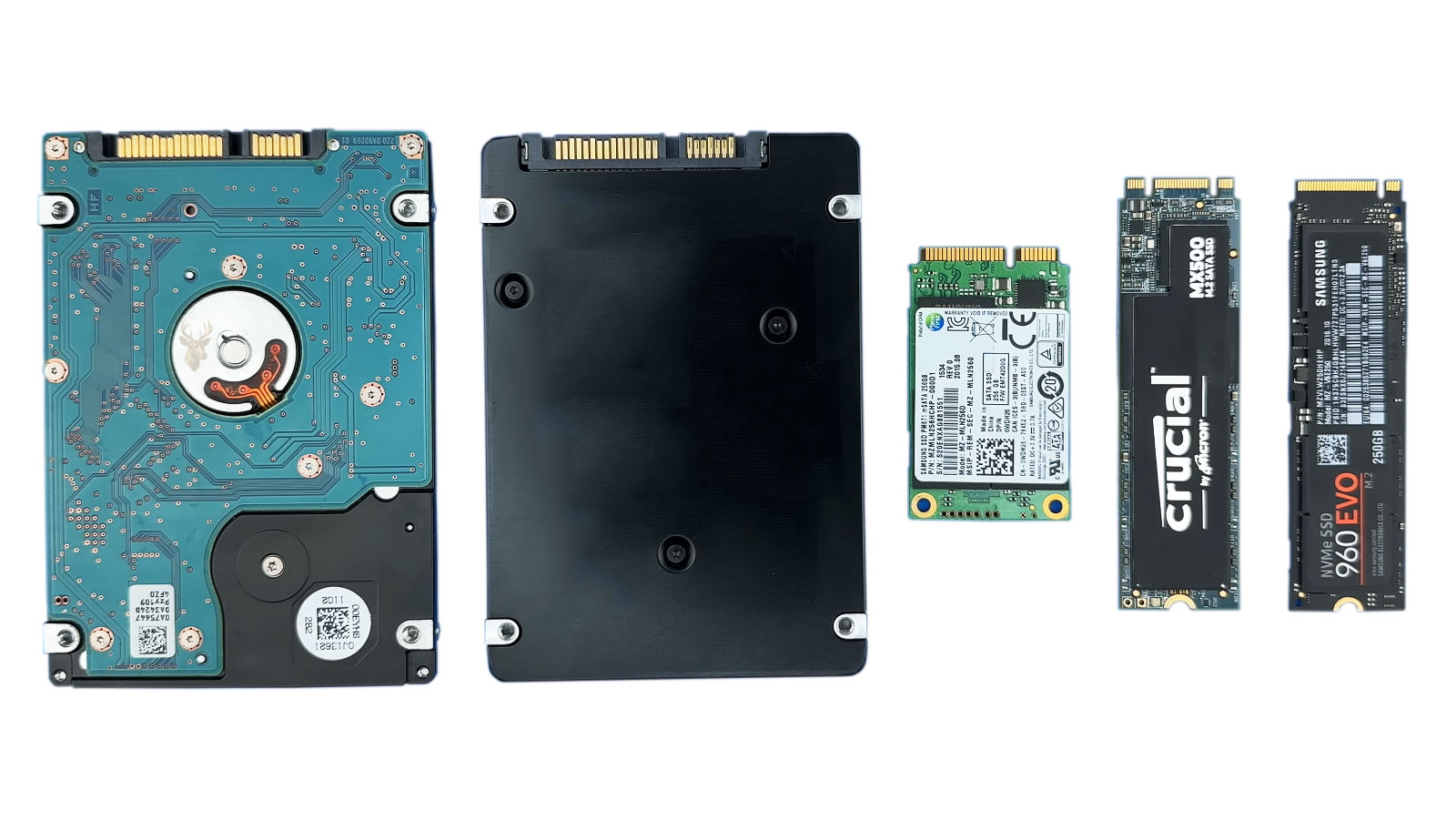
An M.2 Drive Can Fit Into a Computer and Still Be Incompatible
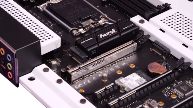
M.2 storage drives are compact circuit boards that connect directly to a motherboard or laptop system board. They eliminate the separate data and power cables commonly used by 2.5-inch SATA drives, but their small size does not make compatibility simple.
Two M.2 drives may look nearly identical while using different communication standards. One may operate through the SATA interface, while another uses PCI Express lanes and the NVMe protocol. A motherboard slot may support one type, both types, or neither type despite having a connector that appears correct.
Physical length, connector notches, available PCI Express lanes, firmware support, and motherboard design all influence whether the drive can be installed and detected. The shape of the drive alone does not confirm compatibility.
An M.2 connector describes a physical format. It does not guarantee that every drive using that format can communicate with the computer.
M.2 Describes the Form Factor Rather Than One Storage Technology
The term M.2 refers primarily to the physical card and connector format. M.2 devices can support storage, wireless networking, cellular communication, and other functions depending on the slot and system design.
For storage upgrades, the most common distinction is between SATA-based M.2 drives and PCI Express NVMe drives. Both can be built on narrow circuit boards and secured to the motherboard with a single screw.
| M.2 characteristic | What it describes | What it does not confirm |
|---|---|---|
| Physical connector | The edge connection used by the card | The communication interface supported by the slot |
| Card length | The distance from the connector to the mounting point | Whether the motherboard firmware can detect the drive |
| Key notch | The physical alignment and allowed connector positions | Complete electrical compatibility |
| M.2 label | The general form factor | Whether the drive uses SATA or NVMe |
This is why a product description should be reviewed beyond the words M.2 SSD. The interface and supported protocol are equally important.
SATA M.2 Drives Use the Familiar SATA Storage Interface
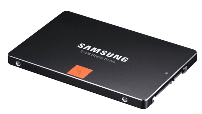
A SATA M.2 SSD communicates through the same general storage interface used by conventional 2.5-inch SATA solid-state drives. The difference is primarily the physical connection and board shape.
Installing the drive directly into an M.2 slot removes the need for a separate SATA data cable and power lead. It does not give the drive the performance characteristics of an NVMe device.
SATA M.2 performance remains limited by the SATA interface. The drive may still provide fast startup and application response compared with a mechanical hard drive, but its maximum transfer rate is generally below that of a properly supported PCI Express NVMe drive.
NVMe Drives Communicate Through PCI Express Lanes
An NVMe M.2 SSD commonly uses PCI Express lanes to communicate more directly with the processor or motherboard chipset. NVMe is designed for solid-state storage and can process many commands efficiently with lower overhead than older SATA storage methods.
The number and generation of available PCI Express lanes influence the maximum possible connection speed. A drive capable of operating through four lanes may function at reduced performance if the system provides fewer lanes or supports an earlier PCI Express generation.
| Drive type | Typical communication path | General performance limitation |
|---|---|---|
| SATA M.2 SSD | SATA controller | Limited by the SATA interface |
| PCIe NVMe M.2 SSD | PCI Express lanes | Limited by lane count, PCIe generation, controller, and drive capability |
| 2.5-inch SATA SSD | SATA cable and controller | Similar interface limit to a SATA M.2 drive |
| PCIe expansion card SSD | PCI Express expansion slot | Depends on slot lanes, firmware, and adapter design |
NVMe capability must exist in both the drive and the computer. An NVMe label on the SSD does not make an unsupported motherboard recognize it.
The Connector Notches Are Known as Keys
The edge connector of an M.2 card can contain one or more notches. These positions are referred to as keys and help limit which cards can be inserted into particular slots.
Storage drives commonly use B-key, M-key, or B-and-M-key connector arrangements. The notch pattern provides useful information, but it should not be treated as a complete compatibility test.
- A B-key position is associated with certain SATA and PCI Express configurations.
- An M-key position is commonly used by PCI Express NVMe storage drives.
- A B-and-M-key drive has two notches and can physically enter more than one connector arrangement.
- The slot wiring and motherboard documentation determine which interface actually works.
A card may slide into a slot because the notches align while remaining unsupported electrically. The key system reduces incorrect installations, but it does not prevent every possible mismatch.
B-and-M-Key Drives Are Often SATA Devices
Many SATA M.2 SSDs use a B-and-M-key edge connector. The two notches allow the drive to fit into slots with compatible physical key positions.
This wider physical compatibility can create confusion. A user may assume that a drive fitting into an M-key slot must operate as an NVMe device, even though the SSD is communicating through SATA and requires the slot to provide SATA support.
If the motherboard’s M.2 slot supports only PCI Express NVMe storage, a SATA B-and-M-key drive may remain undetected despite fitting into the connector and mounting correctly.
An M-Key Slot Does Not Automatically Support Every M-Key Drive
M-key connectors are commonly associated with high-speed PCI Express NVMe drives, often using up to four PCI Express lanes. However, the actual capabilities depend on how the manufacturer wired the slot and what the firmware supports.
Some systems limit the slot to fewer lanes. Others share bandwidth with expansion slots, SATA ports, or onboard devices. Older motherboards may detect an NVMe drive only as secondary storage and may not support starting the operating system from it.
The key shape explains where a card can connect. The motherboard design explains what the connection can do.
Card Length Is Identified by a Four- or Five-Digit Number
M.2 storage sizes are commonly written as numbers such as 2230, 2242, 2260, 2280, or 22110. The first two digits describe the approximate width in millimeters, while the remaining digits describe the length.
| M.2 size | Approximate width | Approximate length | Common use |
|---|---|---|---|
| 2230 | 22 millimeters | 30 millimeters | Compact systems and selected specialized devices |
| 2242 | 22 millimeters | 42 millimeters | Small laptops, embedded computers, and compact systems |
| 2260 | 22 millimeters | 60 millimeters | Less common storage configurations |
| 2280 | 22 millimeters | 80 millimeters | Common desktop and laptop storage size |
| 22110 | 22 millimeters | 110 millimeters | Selected workstation and enterprise storage devices |
A slot may electrically support the drive while lacking a mounting point for its length. The card should not be left unsecured or bent to reach an incorrect screw position.
The Mounting Standoff Must Match the Drive Length
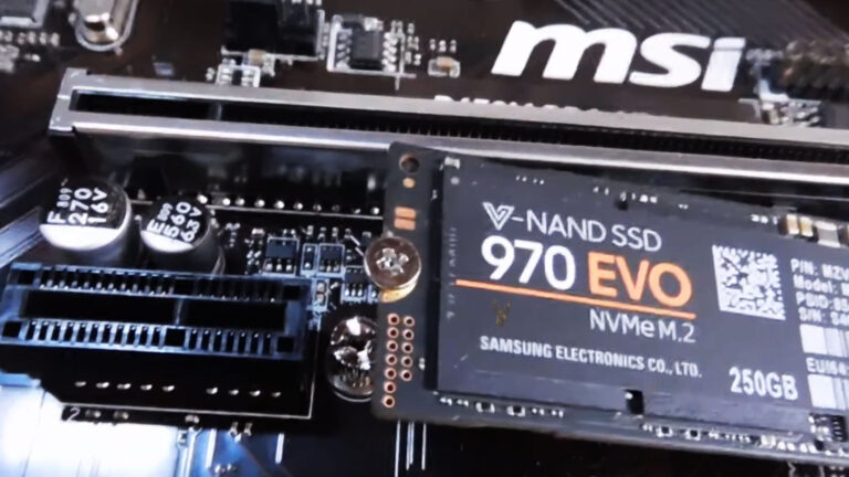
An M.2 drive enters the connector at a slight angle and is then lowered onto a standoff. A small screw or retaining mechanism holds the opposite end of the drive against the motherboard.
Motherboards may provide several standoff positions for different card lengths. Laptops frequently provide only the position intended for the original drive size.
Using the wrong mounting point can bend the circuit board or allow the drive to move. An unsecured drive may lose contact, short against nearby material, or suffer connector damage if the computer is transported.
The Retaining Screw Is Smaller Than Common Computer Screws
M.2 mounting screws are small and can be confused with other screws used in laptops, desktop cases, and storage brackets. A screw with the wrong thread or length can damage the standoff or press against the drive incorrectly.
- Confirm that the correct standoff is installed for the drive length.
- Insert the drive into the connector without forcing it.
- Lower the drive gently until it rests on the standoff.
- Use the correct retaining screw or manufacturer-provided latch.
- Tighten only enough to hold the drive securely.
The screw should not be used to pull a misaligned drive into position. The card and standoff should already align before tightening begins.
Some Slots Support SATA, NVMe, or Both
Motherboard manufacturers can wire an M.2 storage slot for SATA, PCI Express NVMe, or both interfaces. The capabilities may differ between two M.2 slots on the same motherboard.
For example, one connector may support four-lane NVMe drives, while another supports two-lane NVMe and SATA devices. A drive that works in one slot may remain undetected in the other.
| Slot capability | SATA M.2 drive | NVMe M.2 drive |
|---|---|---|
| SATA-only M.2 slot | May operate normally | Usually not detected |
| PCIe NVMe-only M.2 slot | Usually not detected | May operate normally |
| Combined SATA and PCIe slot | May operate normally | May operate normally |
| Non-storage M.2 slot | Not supported | Not supported |
The motherboard manual should identify the supported interface for each connector rather than referring to all M.2 slots as though they are identical.
Wireless M.2 Slots Are Not Storage Slots
Laptops and compact computers may contain an M.2 connector intended for a Wi-Fi and Bluetooth card. This slot can resemble a small storage connector but uses a different key position, card size, and electrical configuration.
A wireless slot is commonly designed for a short card with antenna connections. It should not be assumed to support an SSD simply because both devices use the M.2 form factor.
Attempting to force a storage drive into an incompatible wireless connector can damage the card, slot, or system board.
Shared Resources Can Disable Other Motherboard Connections
An M.2 storage slot may share internal resources with one or more SATA ports or PCI Express expansion slots. Installing a drive can disable another connector even when nothing is physically wrong.
This behavior occurs because the motherboard has a limited number of chipset lanes and controller connections. The manufacturer assigns some of those resources to multiple possible devices, but only one path may operate at a time.
- Installing a SATA M.2 drive may disable a numbered SATA port.
- Using an NVMe slot may reduce the lane width available to an expansion slot.
- A second M.2 connector may operate only when another slot is unused.
- Certain processor models may provide fewer usable storage lanes.
- Firmware settings may determine which shared connection remains active.
A hard drive that disappears immediately after an M.2 upgrade may still be healthy. Its SATA port may have been disabled by the motherboard’s resource-sharing design.
Motherboard Documentation Is More Reliable Than Appearance
The motherboard or computer service manual should be reviewed before purchasing an M.2 drive. It can identify supported interfaces, card lengths, lane allocation, disabled ports, boot limitations, and installation procedures.
Product pages sometimes describe M.2 support without clearly separating SATA and NVMe capability. The complete specifications and storage configuration notes provide a better compatibility reference than a brief marketing summary.
A connector that looks correct is only the beginning of an M.2 compatibility check.
An Existing Drive Should Be Identified Before Replacement
When replacing an installed M.2 drive, its label and specifications should be documented before removal. The model number can reveal whether it uses SATA or NVMe, its physical length, storage capacity, and other characteristics.
Matching the interface is especially important in laptops where the manufacturer may use a connector that physically accepts more than one drive type while supporting only the original configuration.
- Record the computer or motherboard model.
- Identify the existing M.2 drive model number.
- Confirm whether the drive uses SATA or NVMe.
- Measure or verify the card length.
- Review the supported capacity and interface specifications.
- Confirm whether the computer can start from the proposed replacement.
These checks reduce the chance of purchasing a drive that fits physically but remains unavailable to the system.
A Missing Drive Does Not Immediately Prove the SSD Is Defective
When a newly installed M.2 drive does not appear, the failure can involve compatibility, seating, firmware settings, shared motherboard resources, missing storage drivers, or an unsupported partition configuration.
The drive should not be declared defective until the system specifications and installation have been verified. Testing in another confirmed-compatible computer or enclosure can provide a more useful comparison.
A methodical compatibility check prevents a correct drive from being returned when the original system never supported its interface.
Firmware Support Determines Whether the Computer Can Use the Drive
A motherboard can have a physically compatible M.2 slot and still lack complete firmware support for a particular drive. This is especially relevant with older systems that were designed before NVMe storage became common.
The firmware may detect the drive as secondary storage but may not allow the computer to start from it. In other systems, the drive may remain completely absent until a firmware update adds support or corrects a compatibility problem.
| Firmware condition | Possible result |
|---|---|
| Full NVMe support | The drive can be detected and may be available as a startup device. |
| Storage-only support | The drive appears after Windows starts but cannot be selected for startup. |
| Outdated firmware | The drive may be missing, unstable, or identified incorrectly. |
| No NVMe support | A compatible-looking drive may remain completely undetected. |
| Restricted manufacturer firmware | Only selected drive types or capacities may operate correctly. |
Firmware updates should be reviewed carefully because they can also change startup settings, storage modes, and security options.
Older Computers May Detect NVMe Storage Without Booting From It
Some older motherboards can access an NVMe drive after the operating system loads the required driver, yet they cannot use the same drive during the early startup process. The limitation exists because the firmware does not include the instructions needed to read the NVMe device before Windows begins.
In this situation, the drive may work well for files, applications, or secondary storage while remaining unavailable in the startup device list.
Detection inside Windows and support during startup are two separate compatibility questions.
A user planning to move Windows to an NVMe drive must confirm boot support rather than relying only on whether the drive appears in Disk Management.
UEFI and Legacy Startup Modes Can Affect NVMe Installation
Modern NVMe startup configurations commonly depend on UEFI firmware and a compatible partition layout. A computer configured for legacy startup may not present the drive correctly as a boot option even when the hardware supports it.
Changing startup mode without preparation can prevent an existing Windows installation from loading. The operating system’s partition style, firmware mode, and startup files must agree.
- UEFI startup commonly works with GPT partitioned drives.
- Legacy startup commonly depends on older MBR configurations.
- Switching modes can make a previously working installation unavailable.
- Cloned drives may require startup repair if the original configuration differs.
- Secure Boot settings can also influence whether some startup media is accepted.
Firmware changes should be documented before they are made so the original configuration can be restored if necessary.
Cloning a SATA Drive to NVMe Can Introduce Driver and Startup Differences
Moving an existing Windows installation from a SATA drive to an NVMe SSD is not always a direct copy-and-start process. The new storage device uses a different controller path, and the system must have the appropriate driver and startup configuration available.
A clone can complete successfully while the computer still fails to start from the destination drive. The cloned files may be intact, but the firmware entry, partition structure, or startup records may not match the new configuration.
| Post-clone symptom | Possible cause |
|---|---|
| Drive appears but is not bootable | Missing UEFI startup entry or incompatible firmware mode |
| Windows begins loading and then fails | Storage controller driver or startup configuration problem |
| Original drive still starts instead | Boot order remains pointed to the old installation |
| Both drives show duplicate system partitions | Firmware may select the wrong startup entry |
| Drive is absent after cloning | Interface or slot compatibility may be incorrect |
Disconnecting the original drive during the first startup test can help confirm whether the computer is truly using the new installation.
The Operating System May Need a Storage Controller Driver
Most modern versions of Windows include general NVMe support, but some computers use manufacturer-specific storage controllers or RAID modes. In those systems, the installer may not show the M.2 drive until the correct driver is supplied.
This does not necessarily indicate a defective SSD. The drive may be hidden behind a controller that Windows does not yet understand.
- Confirm that the drive appears in the motherboard firmware.
- Check the current storage controller mode.
- Review the computer manufacturer’s driver requirements.
- Load the appropriate storage driver during Windows setup if needed.
- Verify that the correct drive is selected before partitioning.
Changing the controller mode only to make the drive appear can create startup problems for an existing installation and should not be done without understanding the consequences.
RAID and Manufacturer Storage Modes Can Hide Individual Drives
Some laptops and desktops ship with storage configured through RAID, Intel Rapid Storage Technology, or another manufacturer-controlled mode even when only one physical drive is installed.
Under these configurations, Windows may interact with the controller rather than the SSD directly. A replacement drive can remain missing during installation until the correct controller driver is loaded.
The firmware storage mode should not be changed casually. Switching from RAID to AHCI can cause an existing Windows installation to stop starting if the operating system was prepared for the original mode.
Capacity Limits Can Be Imposed by Firmware or System Design
An M.2 slot may support the correct interface and card size while still being limited to selected storage capacities. These restrictions are more common in older laptops, compact systems, and manufacturer-specific designs.
The limitation may involve firmware addressing, thermal design, power delivery, or a validated hardware list. A larger drive can sometimes work despite not being listed, but compatibility should not be assumed.
| Capacity concern | Possible result |
|---|---|
| Drive exceeds documented limit | The system may not detect it or may report the capacity incorrectly. |
| Unsupported double-sided drive | The card may not fit or may contact the system board or cover. |
| High-capacity drive draws more power | Compact systems may experience heat or stability problems. |
| Firmware has limited support | The drive may work only after an update. |
| Manufacturer whitelist or validation limits | Unapproved models may be rejected or behave unpredictably. |
Documentation should be checked for both maximum capacity and any physical restrictions affecting thicker or double-sided drives.
Single-Sided and Double-Sided Drives Need Different Clearance
Some M.2 SSDs place memory chips on one side of the circuit board, while others use both sides. A double-sided drive may be thicker and can interfere with shielding, thermal pads, nearby components, or the bottom cover of a laptop.
The drive may fit into the connector but bend when the cover is installed. Continuous pressure can damage the SSD, connector, or system board.
- Inspect the space beneath the original drive.
- Check whether a thermal pad is designed for a specific thickness.
- Confirm that the replacement does not contact the case.
- Do not force the bottom cover closed over the drive.
- Verify that the SSD remains flat after installation.
Physical clearance is part of compatibility even when the interface and card length are correct.
M.2 Drives Can Produce Significant Heat
High-performance NVMe drives can become much warmer than many SATA M.2 devices, particularly during long transfers, game installations, video work, and system imaging.
When the controller reaches a temperature threshold, it may reduce performance to protect the drive. This behavior is known as thermal throttling.
A fast drive installed without adequate cooling may perform well briefly and slow down during sustained work.
Heat does not always mean the drive is defective. The system’s airflow, heatsink design, thermal pad placement, and workload all influence operating temperature.
A Heatsink Must Fit the Drive and the Computer
Desktop motherboards often include M.2 heatsinks, while some drives are sold with their own cooling covers. Installing both at the same time may create a clearance problem or prevent proper contact.
Laptops frequently rely on thin thermal pads that transfer heat to a metal shield or bottom cover. A thick aftermarket heatsink may prevent the computer from closing correctly.
| Cooling method | Important consideration |
|---|---|
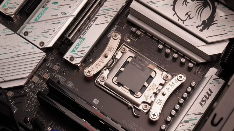
| Motherboard heatsink | The protective film must be removed from the thermal pad. |
| Drive-mounted heatsink | It must not interfere with the motherboard cover or graphics card. |
| Laptop thermal pad | The thickness must match the original design. |
| Open airflow only | Case ventilation must reach the drive area. |
| No cooling provision | Sustained performance may be reduced under heavy activity. |
The cooling solution should make even contact without bending the SSD or placing pressure on its components.
Protective Film on a Thermal Pad Can Prevent Proper Cooling
Thermal pads supplied with motherboard covers and heatsinks often include a thin protective film. If the film is left in place, heat transfer is greatly reduced.
The cover may appear installed correctly while the drive operates hotter than expected. The film should be removed only when the heatsink is ready to be installed so the pad remains clean.
Touching the pad excessively can reduce its ability to make uniform contact with the SSD.
PCI Express Generation Affects Speed but Usually Preserves Compatibility
PCI Express generations provide different maximum transfer rates. A newer NVMe drive can often operate in an older compatible slot, but it will be limited by the slower generation.
For example, a PCIe 4.0 drive installed in a PCIe 3.0 slot may function normally at PCIe 3.0 speeds. The exact result depends on the motherboard, processor, firmware, and drive controller.
| Drive and slot combination | Likely outcome |
|---|---|
| Newer-generation drive in older slot | Usually operates at the older slot’s maximum speed. |
| Older-generation drive in newer slot | Usually operates at the drive’s maximum supported speed. |
| Drive requires more lanes than provided | May operate with reduced performance. |
| Firmware lacks support | May remain undetected despite electrical compatibility. |
Buying the fastest available drive does not guarantee that the computer can use its full performance.
Lane Width Can Reduce Performance Without Preventing Detection
NVMe drives commonly use two or four PCI Express lanes. A four-lane drive may still function in a slot that provides fewer lanes, depending on the system design.
The drive can appear healthy and operate reliably while benchmark results remain below its advertised speed. This is a configuration limit rather than evidence of failure.
- The slot may be electrically limited to two lanes.
- The processor may provide fewer storage lanes than another processor model.
- A second M.2 drive may divide available bandwidth.
- An expansion card may share resources with the storage slot.
- The firmware may negotiate a lower connection width.
Motherboard lane diagrams and storage notes help explain these performance differences.
Adapters Can Add an M.2 Drive but Cannot Create Missing Support
PCI Express adapter cards can allow an M.2 NVMe drive to be installed in a desktop expansion slot. The adapter provides a physical connection between the SSD and the PCI Express slot.
A simple adapter does not add NVMe boot support to firmware that lacks it. It also cannot provide more PCI Express lanes than the expansion slot makes available.
An adapter changes where the drive connects. It does not automatically change what the motherboard understands.
The expansion slot must be electrically large enough, and the motherboard must support the intended use of the drive.
Some Adapter Cards Require PCIe Bifurcation
Multi-drive M.2 adapter cards can hold several NVMe SSDs in one expansion slot. Many of these cards depend on PCI Express bifurcation, which divides a larger group of lanes into separate connections for each drive.
If the motherboard does not support the required lane division, only one drive may appear or none of the drives may work correctly.
| Adapter arrangement | Possible requirement |
|---|---|
| Single-drive passive adapter | One compatible PCIe slot with enough electrical lanes |
| Four-drive passive adapter | Motherboard bifurcation support, often into four groups |
| Adapter with onboard switch | May support more systems but costs more and can add complexity |
| Bootable adapter configuration | Firmware support for NVMe startup through the selected slot |
The adapter documentation and motherboard lane configuration must be reviewed together.
USB Enclosures Must Match the M.2 Interface
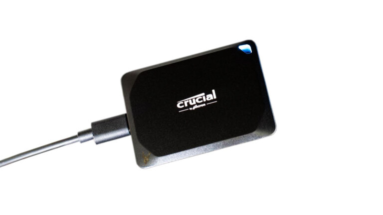
An M.2 USB enclosure can be useful for cloning, file transfer, and testing, but enclosures are not universally compatible with every M.2 storage drive.
Some enclosures support only SATA M.2 devices. Others support only NVMe drives. Combined enclosures exist, but their controller design must explicitly support both interfaces.
- Identify whether the drive is SATA or NVMe.
- Confirm the supported key type and card length.
- Check the enclosure’s maximum capacity and interface.
- Install the correct thermal pad when required.
- Verify that the computer’s USB port provides the expected speed.
A drive that remains missing in an incompatible enclosure may still be completely functional.
USB Speed Can Limit an Otherwise Fast NVMe Drive
An NVMe drive connected through USB cannot operate at the same speed it may reach through a direct PCI Express connection. The enclosure controller and USB port become the limiting parts of the storage path.
A high-performance drive may therefore show modest transfer rates when used through an older USB port. This is expected and does not indicate that the SSD is running incorrectly.
Cable quality, port generation, thermal throttling, and enclosure controller capability can all affect external performance.
Compatibility Testing Should Follow a Defined Order
When an M.2 drive is not detected, random changes can make the problem harder to identify. A structured process separates physical installation, interface compatibility, firmware support, and operating system configuration.
- Confirm the drive’s exact model, interface, key type, and length.
- Verify the slot’s supported interface and mounting size.
- Reseat the drive and inspect the connector.
- Check whether the drive appears in firmware.
- Review shared port and lane restrictions.
- Confirm controller mode and driver requirements.
- Test the drive in another known-compatible system or enclosure.
This order helps determine whether the problem belongs to the drive, the slot, the firmware, or the software configuration.
Secure Boot Can Affect Whether an Installation Starts
Secure Boot is designed to allow trusted startup software to run during the early stages of the boot process. It does not normally determine whether an M.2 drive is physically detected, but it can affect whether an operating system or recovery environment starts from that drive.
A newly cloned or manually installed drive may appear in firmware while the computer refuses to start from it. The problem may involve unsigned startup files, an incompatible operating system, or a mismatch between the existing Secure Boot configuration and the new installation.
- The drive may appear in firmware but not start the operating system.
- Recovery media may be rejected even though the USB device is detected.
- A cloned installation may require a corrected UEFI startup entry.
- Disabling Secure Boot temporarily may help with diagnosis but should not be treated as the final repair automatically.
- The original security settings should be documented before changes are made.
Startup security and storage compatibility should be evaluated separately. A detected drive can still have an invalid startup configuration.
BitLocker Can Complicate Drive Replacement and Cloning
BitLocker encryption can protect data stored on an M.2 drive, but hardware changes may cause Windows to request the recovery key. Replacing the drive, changing firmware settings, switching controller modes, or altering Secure Boot can change the system measurements used to unlock the encrypted volume automatically.
A clone of an encrypted drive may not behave exactly like the original installation. The recovery key should be confirmed before the original drive is removed or major firmware changes are attempted.
A successful physical installation does not remove the need for the correct encryption credentials.
Without the recovery key, a technically healthy replacement process can still leave the user unable to access protected files.
Drive Encryption Can Limit Testing in Another Computer
Moving an encrypted M.2 drive to another computer can confirm whether the device is detected, but it may not provide immediate access to the files. The second computer may show the partition while requiring a password or recovery key before the contents can be opened.
This distinction matters during troubleshooting. Detection confirms that the hardware and enclosure can communicate with the SSD. It does not confirm that the data is unencrypted or accessible without authorization.
| Test result | What it confirms | What it does not confirm |
|---|---|---|
| Drive appears in another computer | The SSD can communicate through that connection | The original motherboard slot is working correctly |
| Encrypted partition is visible | The partition structure can be read | The files can be opened without the recovery key |
| Files open after unlocking | The data remains accessible | The original computer can start from the drive |
| Drive remains undetected | A hardware or compatibility problem may still exist | The SSD is necessarily defective |
A Drive May Need to Be Initialized Before Windows Displays It
A new M.2 drive can be detected by the motherboard and Windows while remaining absent from File Explorer. This often occurs because the drive has not been initialized, partitioned, formatted, or assigned a drive letter.
Disk Management may show the device as unallocated or offline. Initializing and formatting the wrong disk can erase access to existing data, so the drive model and capacity should be confirmed before any changes are made.
- Open Disk Management and identify the new drive by model or capacity.
- Confirm that it does not contain needed data.
- Select the appropriate partition style for the intended system.
- Create the required volume or volumes.
- Format the volume with the appropriate file system.
- Assign a drive letter if Windows does not assign one automatically.
A missing drive letter is a software configuration issue, not proof that the M.2 slot or SSD has failed.
GPT Is Commonly Used With Modern M.2 System Drives
GUID Partition Table, commonly called GPT, is widely used for modern Windows installations that start through UEFI firmware. It supports large drives and provides a structure suited to current startup environments.
An older MBR partition layout may still work for secondary storage or legacy startup configurations, but it can create limitations when the goal is to install Windows in modern UEFI mode.
| Partition style | Common use | Important consideration |
|---|---|---|
| GPT | Modern UEFI systems and large-capacity drives | Usually preferred for current Windows startup installations |
| MBR | Older legacy BIOS systems | Can limit drive size and primary partition count |
| Existing manufacturer layout | Factory recovery and diagnostic partitions | Cloning may require all necessary partitions to be copied |
| Uninitialized drive | New or erased storage device | Will not appear as usable file storage until configured |
The partition style should match the computer’s firmware mode and intended use rather than being selected without checking the startup configuration.
Cloning Software Must Copy the Required Startup Partitions
A Windows system drive usually contains more than the visible C drive. It may also include an EFI System Partition, recovery partition, manufacturer tools, and reserved areas used during startup and maintenance.
Copying only the main Windows partition can leave the destination drive without the files needed to start. A complete system clone should include the required boot and recovery partitions unless a clean installation is planned.
- EFI System Partition stores UEFI startup files.
- Windows partition contains the operating system and user data.
- Recovery partition provides repair and reset tools.
- Manufacturer partitions may include diagnostics or factory recovery files.
- Reserved partitions can support Windows disk management functions.
The destination drive can contain all user files and still fail to start if the required startup partitions were omitted.
The Destination Drive Must Have Enough Usable Capacity
A replacement M.2 drive advertised with the same general capacity as the original may provide a slightly different number of usable sectors. Cloning software can reject the destination if it is even slightly smaller than the source layout.
The amount of data stored on the source is not the only consideration. The total partition structure must fit unless the cloning software can safely resize the partitions during the copy.
Two drives sold under the same capacity label do not always provide exactly the same usable space.
Checking exact capacity before cloning can prevent a long copy process from failing near the end.
Drive Health Should Be Checked Before Migration
A storage upgrade is often planned because the original drive is slow, nearly full, or showing errors. Cloning from an unhealthy source can transfer corrupted files or stop repeatedly when unreadable areas are encountered.
Before migration, the source drive should be evaluated for communication errors, media problems, overheating, and file system damage. Important files should be backed up separately rather than relying entirely on one clone operation.
| Source condition | Migration concern |
|---|---|
| Healthy but nearly full | Partition resizing and free space planning may be required. |
| Communication errors | The enclosure, cable, or source connection may interrupt cloning. |
| Uncorrectable media errors | Some files or sectors may not copy successfully. |
| File system corruption | The clone may reproduce logical damage. |
| Severe overheating | The drive may throttle or disconnect during a long copy. |
A Clean Installation Avoids Some Cloning Problems
Installing Windows fresh on the new M.2 drive can avoid old startup records, inherited file system damage, unnecessary software, and controller settings copied from the previous storage device.
A clean installation requires programs to be reinstalled and user files to be restored from backup. Application licenses, email archives, browser data, and specialized settings should be documented before the original drive is erased or removed from service.
The better approach depends on the condition of the original installation, the amount of configuration that must be preserved, and whether the computer’s startup environment is changing from SATA to NVMe.
Laptop Battery Power Should Be Disconnected Before Installation
Removing the charger does not always remove electrical power from a laptop system board. The internal battery may continue supplying voltage to the M.2 slot and nearby components.
When the computer design allows it, the internal battery should be disconnected before the SSD is removed or installed. Some systems provide a firmware option or service procedure for disabling the battery temporarily.
- Shut down the computer completely.
- Disconnect the charger and external devices.
- Follow the manufacturer’s procedure for opening the case.
- Disconnect or disable the internal battery when specified.
- Discharge static electricity before touching the SSD or system board.
- Reconnect the battery only after the drive is secured and inspected.
Working on an energized board increases the risk of short circuits and component damage.
Static Electricity Can Damage an Exposed M.2 Drive
An M.2 SSD has exposed circuitry and connector contacts. Electrostatic discharge can damage the drive controller, memory chips, or motherboard interface even when no spark is visible.
The drive should be handled by its edges and placed on an antistatic surface when it is outside the computer. The gold connector contacts and electronic components should not be touched unnecessarily.
The small size of an M.2 drive makes it easy to handle, but its exposed electronics still require careful protection.
The Drive Must Be Inserted Fully Before It Is Secured
An M.2 drive normally enters the connector at an angle before being lowered toward the standoff. If it is only partially inserted, the mounting hole may still appear close enough for the screw to catch.
Using the retaining screw to pull the drive backward or force it flat can leave the edge connector incompletely seated. The SSD may remain undetected or disconnect intermittently.
- The connector contacts should enter evenly.
- The drive should not require excessive insertion force.
- The mounting hole should align naturally with the standoff.
- The board should remain flat after the screw is installed.
- No part of the drive should contact an unrelated component.
If alignment is incorrect, the drive should be removed and the slot, key position, and card length should be checked again.
Overtightening the Screw Can Bend the Circuit Board
The retaining screw is intended only to hold the drive against the standoff. Excessive tightening can bend the SSD, damage the mounting hole, strip the standoff, or place pressure on memory packages.
The screw should be secure but not forced. Manufacturer latch systems should also be positioned carefully so they hold the drive without pressing against components not designed to carry mechanical load.
Thermal Pads Must Not Cover the Wrong Components
A thermal pad should contact the intended heat-producing areas of the SSD and the heatsink surface. A pad that is too thick can bend the drive, while one that is too thin may leave an air gap.
Some SSD labels are designed to remain attached and may help spread heat. Removing a manufacturer label without instructions can damage components or affect warranty coverage.
| Thermal installation error | Possible result |
|---|---|
| Protective film remains attached | Heat transfer is reduced. |
| Pad is too thick | The SSD may bend when the heatsink is tightened. |
| Pad is too thin | It may not contact both surfaces. |
| Heatsink is misaligned | Cooling pressure may be uneven. |
| Drive label is removed unnecessarily | Components or warranty markings may be damaged. |
Benchmark Results Should Be Interpreted in Context
A newly installed NVMe drive may produce lower benchmark numbers than those shown in product advertising. The computer may use an older PCI Express generation, fewer lanes, a chipset-connected slot, or a thermal design that limits sustained performance.
Available free space, background activity, encryption, power settings, and test file size can also affect the result. One benchmark should not be used alone to declare the installation defective.
- Confirm the negotiated PCI Express generation.
- Check the number of active lanes.
- Monitor drive temperature during the test.
- Compare the slot used with the motherboard manual.
- Repeat the test after background activity has settled.
Reliable operation and appropriate performance for the system are more meaningful than matching a best-case laboratory result.
Power Management Can Affect NVMe Stability
NVMe devices use power-saving states to reduce energy consumption and heat. In some systems, firmware, controller, or driver problems can cause the drive to respond slowly or disappear when entering or leaving a low-power state.
The symptoms may appear after sleep, during idle periods, or immediately after the computer wakes. Firmware updates, chipset drivers, SSD firmware, and power settings may all be relevant.
A drive that works during heavy use but disappears after idle time may have a power-state problem rather than a bandwidth limitation.
SSD Firmware Updates Can Correct Compatibility Problems
Drive manufacturers sometimes release firmware updates to improve stability, power management, thermal behavior, and compatibility with specific controllers.
An update should be performed only with stable power and a current backup. Interrupting drive firmware installation can leave the SSD unusable.
- Confirm the exact SSD model and current firmware version.
- Review the manufacturer’s release notes.
- Back up important files.
- Connect the computer to reliable power.
- Close unnecessary applications.
- Follow the manufacturer’s update procedure without interruption.
A firmware update should address a documented issue rather than being applied randomly during unrelated troubleshooting.
Motherboard Firmware Updates May Change Storage Behavior
A motherboard firmware update can add support for newer drives, correct lane allocation problems, improve startup compatibility, or resolve detection failures. It can also reset storage settings and boot order.
After an update, controller mode, Secure Boot, UEFI startup settings, and disabled SATA ports should be checked before assuming the M.2 drive has failed.
| Post-update change | Possible effect |
|---|---|
| Boot order reset | The computer starts from the wrong drive or finds no valid entry. |
| RAID mode changed | Windows may fail to start or the installer may not see the drive. |
| Secure Boot restored | Older or unsigned startup media may be rejected. |
| Shared port setting changed | A SATA device or expansion slot may become unavailable. |
| New NVMe support added | A previously unsupported drive may become detectable. |
A Drive That Disappears Under Load May Be Overheating
Thermal throttling normally reduces performance before a drive reaches a dangerous temperature. Severe heat, poor heatsink contact, or controller instability can cause a drive to reset or disappear under sustained activity.
The problem may occur during cloning, large game installations, video rendering, or long file transfers. The drive may return after the computer cools or restarts.
- Monitor temperature during sustained writes.
- Confirm that the heatsink contacts the drive correctly.
- Inspect airflow around the M.2 slot.
- Check whether a graphics card blocks ventilation.
- Compare behavior with the side panel installed and removed.
Repeated thermal resets should be corrected before the drive is trusted with important work.
A Drive Can Be Healthy but Unsupported by the Slot
Testing the SSD in another confirmed-compatible computer or enclosure can help determine whether the device itself is functional. A successful test elsewhere suggests that the original slot, firmware, or system configuration requires further attention.
The comparison must use hardware that supports the same interface. Testing an NVMe drive in a SATA-only enclosure or a SATA M.2 drive in an NVMe-only adapter provides no useful conclusion.
A valid compatibility test requires a second connection that is known to support the exact drive type.
A Known-Good Drive Can Help Test the Original Slot
If another compatible M.2 drive works in the original slot, the first SSD becomes more suspect. If both drives remain undetected, the slot, firmware settings, shared resources, or motherboard may be responsible.
The known-good drive should contain no irreplaceable data because firmware tests, initialization prompts, and accidental formatting can create unnecessary risk.
| Comparison result | Likely direction |
|---|---|
| Original drive works in another compatible system | Inspect the original computer’s slot and configuration. |
| Known-good drive works in the original slot | The original SSD may be incompatible or defective. |
| Neither drive works in the original slot | The slot, firmware, or motherboard may be involved. |
| Original drive fails in every compatible system | The SSD itself becomes a stronger suspect. |
Important Data Changes the Safe Testing Approach
A failing M.2 drive can lose accessibility quickly, especially when the controller or flash memory is unstable. Repeated benchmarks, firmware updates, repair commands, and cloning attempts may place additional stress on a device containing the only copy of important data.
When valuable files are involved, the priority should be creating a safe copy rather than proving every possible cause. A stable compatible connection should be used, and unnecessary writes to the original drive should be avoided.
- Do not initialize a drive that previously contained needed files.
- Avoid formatting or repartitioning during diagnosis.
- Do not run repeated benchmarks on an unstable SSD.
- Preserve encryption keys before moving the drive.
- Consider professional recovery when the drive disconnects repeatedly or is not detected anywhere.
Final Verification Should Include Startup, Sleep, and Sustained Use
A successful installation requires more than seeing the drive once in firmware. The computer should start correctly, remain stable during extended transfers, recover from sleep, and retain the expected drive detection after several restarts.
- Confirm the drive model and capacity in firmware.
- Verify that Windows identifies the correct interface and volume size.
- Check startup order and confirm the intended drive is being used.
- Test sleep and wake behavior.
- Perform a controlled sustained transfer.
- Monitor temperature and communication errors.
- Restart and cold-start the computer more than once.
The case should be fully assembled during final testing because covers, thermal pads, and nearby components can change cooling and physical pressure.
M.2 Compatibility Requires More Than Matching the Connector
A reliable M.2 upgrade depends on the drive interface, key type, physical length, mounting position, lane availability, firmware support, startup mode, controller configuration, cooling, and operating system preparation.
The drive may fit into the slot while remaining unsupported, may operate at reduced speed because of lane limits, or may require firmware and driver changes before Windows can use it. Checking each layer before installation prevents unnecessary returns, failed clones, damaged connectors, and avoidable data loss.
When the physical installation, firmware configuration, operating system, and cooling system all match the drive’s requirements, an M.2 SSD can provide compact and dependable storage without the uncertainty created by appearance-based compatibility decisions.