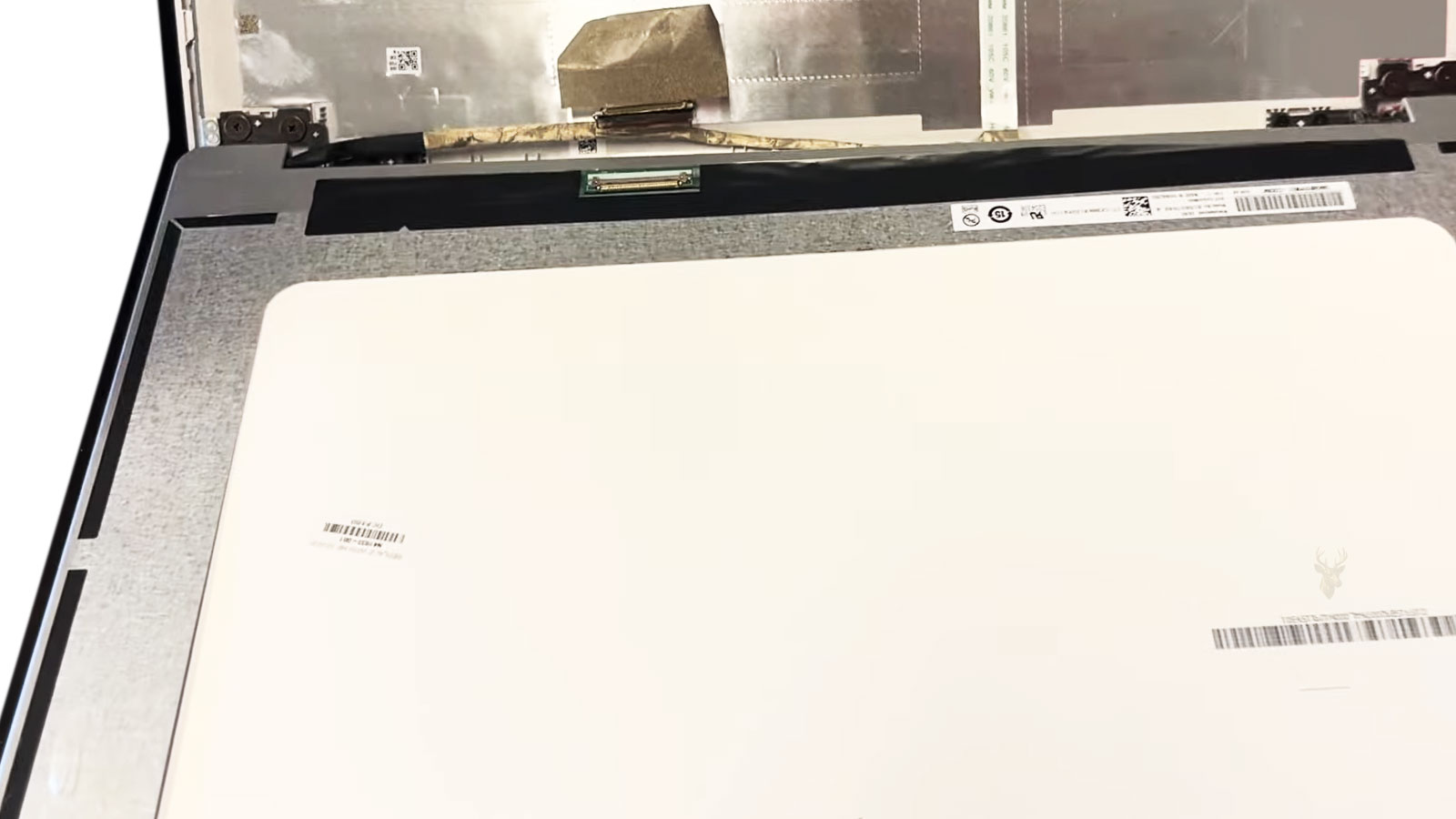
A Display Panel Is Only One Part of the Video Path
When a computer screen begins flickering, briefly turning black, showing unusual colors, or recovering after the lid is moved, the display itself is often blamed first. While the LCD or OLED panel can certainly fail, it represents only the final component in a much longer video path.
Between the graphics processor and the screen are connectors, flexible display cables, hinge routing, protective shielding, voltage circuits, and timing electronics. A defect anywhere along that route may interrupt the picture while leaving the display panel completely functional.
Replacing the screen without confirming the condition of the signal path can result in unnecessary expense while the original problem continues exactly as before.
Repeated Lid Movement Places Constant Stress on Display Cables
Unlike many internal cables that remain stationary throughout the life of a computer, display cables bend every time the lid is opened or closed. Thousands of normal movements gradually flex the same conductors in nearly the same location.
Eventually, individual conductors inside the cable may weaken without any visible damage to the outer insulation. Because the cable is still physically connected, the screen may continue working most of the time before beginning to exhibit intermittent failures.
- The image disappears only at certain lid angles.
- Opening the screen farther restores the picture.
- Closing the lid slightly changes the display immediately.
- The problem becomes more frequent over several months.
- No external damage is visible on the cable itself.
These observations suggest that movement influences the electrical connection rather than indicating an immediate failure of the display panel.
Digital Video Signals Depend on Stable Electrical Connections
Modern display interfaces transfer large amounts of digital information at very high speed. Small interruptions that might seem insignificant in another circuit can prevent accurate image transmission between the motherboard and display assembly.
A connector that shifts slightly, develops oxidation, or loses contact on one signal line may create symptoms ranging from occasional flickering to complete loss of the picture. Depending on which conductors are affected, the backlight may continue operating while image data disappears, or the image may remain visible under certain conditions before failing again.
A stable picture depends as much on reliable signal delivery as it does on the quality of the display itself.
Because video information travels continuously while the computer is operating, even brief interruptions may become immediately visible to the user.
The Exact Symptom Often Changes as Cable Damage Progresses
Display cable problems rarely remain identical throughout their development. Early symptoms may appear only occasionally, while later failures become easier to reproduce and eventually permanent.
| Observed Display Behavior | Possible Direction for Inspection |
|---|---|
| Brief black screen while moving the lid | Flexing cable near the hinge area. |
| Colored lines that appear intermittently | Unstable digital signal transmission. |
| Image returns after adjusting the screen angle | Mechanical movement affecting cable continuity. |
| Random flashes without software errors | Physical connection rather than operating system behavior. |
| Permanent loss of image after months of intermittent problems | Cable damage may have progressed to a complete open circuit. |
Recording how the symptoms have changed over time often provides valuable information before the computer is opened for inspection.
Connector Seating Is Just as Important as Cable Condition
A perfectly healthy display cable cannot deliver a reliable signal if one end is not fully seated. Modern display connectors often use locking tabs, adhesive retainers, or pressure brackets to prevent movement during normal use.
If the connector was disturbed during previous service, partially inserted during reassembly, or allowed to shift after an impact, the electrical contact may become unreliable even though the cable itself remains undamaged.
- Verify that the connector is fully inserted.
- Inspect locking mechanisms for damage.
- Check for bent or contaminated contacts.
- Confirm that adhesive retainers remain secure.
- Ensure the cable follows its intended routing path.
A connector that appears only slightly loose may still interrupt multiple high-speed video signals simultaneously.
Physical Damage Can Remain Hidden Beneath the Outer Insulation
The protective covering surrounding a display cable is designed to shield delicate conductors from abrasion and handling. Unfortunately, the conductors inside may fatigue or fracture long before the exterior shows visible wear.
This hidden damage explains why some cables appear nearly new while producing intermittent image failures. Visual inspection alone cannot always confirm electrical integrity when repeated bending has weakened internal conductors.
The condition of a display cable cannot always be judged by its appearance.
Mechanical movement, symptom consistency, and electrical testing together provide a more reliable assessment than appearance alone.
Hinge Resistance Can Pull a Cable Away from Its Intended Position
A display cable is normally routed through a narrow area near one or both hinges. The cable must move enough to follow the lid while remaining protected from sharp edges, brackets, and rotating hinge parts.
When a hinge becomes unusually stiff, the force required to open the screen can transfer into the surrounding cable path. The cable may be stretched, twisted, or pressed against the chassis each time the lid moves. A broken hinge mount can create the same problem by allowing parts of the enclosure to shift away from their original alignment.
- The lid requires more force than it did previously.
- A clicking or cracking sound occurs near the hinge.
- The bezel separates slightly while the screen is moved.
- The picture changes at the same point in the lid’s travel.
- The problem began after a drop or impact near a rear corner.
Replacing only the cable may provide temporary improvement if the damaged hinge continues placing abnormal stress on the new part. The mechanical cause and the electrical symptom should be corrected together.
Cable Routing Determines Where Pressure and Bending Occur
Manufacturers shape display cables to follow a specific route through the enclosure. Small folds, adhesive points, fabric tabs, shields, and channels keep the cable away from moving hardware and prevent it from being compressed when the case is closed.
After a screen, hinge, camera, or wireless antenna repair, the cable may be returned through a slightly different path. A few millimeters of misalignment can place a reinforced section outside the hinge channel or move a delicate section directly beneath a cover screw.
A cable that is folded more sharply than intended may work immediately after reassembly and fail later as repeated movement weakens the conductors at the new bend.
Correct routing is part of the repair, not merely a matter of making the cable fit inside the case.
Before the enclosure is closed, the cable should be compared with its original shape, mounting points, and clearance around the hinges.
Image Data and Backlight Power Can Fail Independently
A screen can appear black for more than one electrical reason. The panel may stop receiving image data while its backlight remains on, or the image may still be present while the backlight circuit no longer illuminates it.
These two conditions can look similar from a normal viewing position. Examining the screen under a bright light may reveal a very faint desktop or startup image, indicating that video information is reaching the panel even though illumination is missing.
| Screen Condition | What It May Suggest |
|---|---|
| Screen glows but shows no picture | Image data, panel timing, or signal connection may be interrupted. |
| A faint image is visible under direct light | The backlight power or control path may have failed. |
| The image and illumination disappear together | A shared cable, connector, power source, or panel problem may be involved. |
| Brightness changes when the lid moves | Backlight conductors or connector contacts may be unstable. |
| Colors distort while brightness remains steady | One or more video signal paths may be losing integrity. |
Separating illumination from image transmission prevents every black-screen complaint from being treated as the same failure.
Colored Lines Can Result from Missing Signal Information
Vertical lines, blocks of incorrect color, sparkling pixels, and sections of distorted image are often associated with a damaged panel. However, unstable signal conductors can produce similar results when part of the digital information fails to reach the screen correctly.
The pattern may change when the cable is moved because different conductors make or lose contact. A panel defect is often more consistent, although pressure, temperature, and internal panel connections can also make panel failures intermittent.
- Observe whether the distortion appears before the operating system loads.
- Move the lid slowly without pressing directly on the display surface.
- Compare the built-in screen with an external monitor.
- Capture a screenshot while the distortion is visible.
- View the screenshot on another working display.
If the saved screenshot looks normal elsewhere, the graphics system likely created the image correctly and the fault may be located after the framebuffer, within the internal display path. If the distortion appears in the screenshot as well, the problem may originate earlier in graphics processing or software.
An External Monitor Provides a Useful Comparison but Not a Complete Answer
A normal picture on an external monitor shows that the computer can generate usable video through at least one output path. This makes the internal screen, cable, connector, and associated circuitry more likely areas of investigation.
External and internal displays do not always use the same connector, voltage source, signal routing, or control circuitry. A working external image therefore does not prove that every graphics-related component on the motherboard is healthy.
Some failures affect only the internal display output while external video remains normal. Others appear only after the graphics processor changes power state, resolution, refresh rate, or workload.
An external monitor narrows the search, but it does not automatically identify the failed part.
The comparison is most useful when combined with lid movement, connector inspection, pre-boot behavior, and testing with a known-good internal display component.
Pressure on the Bezel Can Temporarily Change an Internal Connection
Some users discover that pressing a corner of the bezel or lightly twisting the display assembly restores the image. This reaction indicates that physical movement is influencing an electrical connection, but it does not identify whether the fault lies in the cable, panel connector, panel circuitry, or surrounding structure.
Repeated pressure is not a safe repair method. It can crack the display, damage internal layers, separate adhesive, or worsen a loose connection that was previously recoverable.
- Do not press directly on visible LCD areas.
- Avoid twisting the display to reproduce the fault aggressively.
- Note which edge or corner affects the image.
- Inspect mounting screws and bezel alignment.
- Check whether the panel connector is held securely.
The location where pressure changes the symptom can help direct inspection, but the assembly should be opened and tested rather than repeatedly flexed from the outside.
Connector Contamination Can Disturb High-Speed Signals
Dust, adhesive residue, oxidation, and traces of moisture can interfere with the closely spaced contacts inside a display connector. The connector may still appear seated while one or more signal paths remain electrically unreliable.
Liquid exposure near the keyboard or hinge area can travel farther than the visible spill location. Residue may reach the motherboard-side connector, collect beneath retaining tape, or affect the display end of the cable inside the lid.
Cleaning must be performed with power removed and the battery disconnected when the design allows. Scraping contacts, inserting metal objects, or reconnecting a contaminated cable under power can create additional damage.
When corrosion has removed contact plating or damaged connector pins, cleaning alone may not restore a dependable connection. The affected connector, cable, or board area may require replacement or circuit repair.
Display Connections Should Not Be Handled While Power Is Present
Internal display connectors can carry panel power, backlight power, and sensitive communication signals. Disconnecting or inserting the cable while the battery or charger remains connected can create a brief short between adjacent contacts.
A small spark may damage a backlight fuse, power switch, connector pin, or signal component on the motherboard. The original cable problem can then become a second failure involving the board itself.
- Shut the computer down completely.
- Disconnect the charger and external devices.
- Disconnect the internal battery before touching the display cable.
- Confirm connector orientation before reinsertion.
- Secure the cable before restoring power.
Sleep mode is not the same as full electrical disconnection. A sleeping computer may still supply power to portions of the display circuit.
A Known-Good Part Helps Separate the Cable from the Panel
When visual inspection and movement tests remain inconclusive, substitution with a verified compatible component can narrow the fault. A known-good cable may reveal whether the original cable was interrupting the signal, while a known-good panel can expose a defect inside the display assembly.
Compatibility must include the connector, pin arrangement, resolution, refresh requirements, backlight system, mounting design, and model revision. A panel that fits physically may still produce no image or unstable behavior if its electrical requirements differ.
The test component should be connected securely and protected from contact with metal surfaces. Temporary testing should not involve forcing incompatible connectors or operating the display assembly in a position that strains the cable.
A substitution test is valuable only when the replacement part is known to be functional and correct for the system.
The Repair Must Remain Stable Across the Full Range of Lid Movement
A display that works while the computer is stationary has not been fully tested if the original complaint involved lid position. The screen should remain stable as the lid is moved slowly from nearly closed to its normal maximum opening angle.
The test should be repeated after the bezel, hinge covers, bottom panel, and cable retainers are installed. Reassembly can change cable tension and recreate a problem that was absent while the computer was open.
- Watch for flashes, color shifts, and momentary blackouts.
- Confirm that brightness remains steady.
- Check that the webcam and microphone still function if they share the same route.
- Listen for rubbing or clicking near the hinge.
- Verify that the lid closes without pulling or pinching the cable.
A dependable repair restores both the electrical connection and the mechanical conditions that protect it during ordinary use.
Display Problems That Appear Only After Warm-Up May Involve Expansion
A computer may begin with a normal image and develop flickering, lines, or temporary blackouts after several minutes of use. Heat causes metal, plastic, solder joints, and cable materials to expand slightly, and that movement can affect a connection that is already weakened.
As the display assembly warms, a fractured conductor may separate enough to interrupt the signal. A loose connector contact can behave similarly. Once the computer cools, the materials contract and the image may return, making the problem appear inconsistent.
- The screen works normally immediately after a cold start.
- Distortion develops after the computer has been operating for a while.
- The problem becomes more noticeable during demanding work.
- Closing the system and allowing it to cool temporarily restores the picture.
- Moving the lid changes the failure after the machine is warm.
A temperature-related pattern does not automatically identify the cable, but it shows that physical or electrical conditions are changing as the computer warms.
Interference and Poor Shielding Can Affect Image Stability
Display cables are designed with shielding and controlled internal construction because high-speed video signals can be disturbed by electrical noise. Damage to the shielding, incorrect routing, or a replacement cable with poor construction can reduce signal integrity even when every conductor still has continuity.
The screen may show sparkling pixels, brief flashes, horizontal noise, or instability that becomes worse when the processor, graphics hardware, wireless system, or charging circuit is active. These symptoms can resemble a failing panel because the interference appears directly in the image.
A cable can remain electrically connected while no longer carrying high-speed video data cleanly.
This is one reason a basic continuity test cannot confirm every display cable fault. The cable must also preserve the signal quality required by the display interface.
A Replacement Cable Can Introduce a Different Display Failure
Two display cables may have similar connectors and nearly identical shapes while supporting different panel revisions, resolutions, touch functions, camera assemblies, or motherboard layouts. Installing the wrong cable can create a new symptom instead of correcting the original one.
The computer may produce no image, unstable brightness, missing webcam operation, incorrect touch response, or a picture that appears only at certain resolutions. A cable that was removed from a related model should not be assumed compatible without comparing its part number and intended configuration.
| Compatibility Detail | Why It Matters |
|---|---|
| Connector position | The cable must reach both ends without stretching or sharp folding. |
| Pin arrangement | Similar-looking connectors may carry different signals or voltages. |
| Panel resolution | Higher-resolution panels may require a different signal configuration. |
| Touchscreen support | Touch-enabled displays may include additional communication paths. |
| Camera and microphone routing | Some cable assemblies carry more than display signals. |
| Model revision | Internal changes can occur within the same product family. |
Part-number verification is more dependable than choosing a replacement based only on appearance.
Motherboard-Side Damage Can Mimic a Defective Cable
The display connector on the motherboard is exposed to stress whenever the cable is removed, inserted, or pulled at an angle. Bent contacts, cracked solder joints, damaged retaining brackets, and lifted pads can interrupt the same signals carried by the cable.
A replacement cable will not correct a connector that has separated from the board. The new part may appear to fit securely while one or more motherboard contacts remain electrically disconnected beneath the connector housing.
- Inspect the connector under adequate magnification.
- Check whether the housing sits flat against the motherboard.
- Look for bent contacts, discoloration, or missing plastic guides.
- Observe whether the connector moves when the cable is handled.
- Examine nearby fuses, filters, and signal components when damage is suspected.
Board-level repair may be required when the connector or surrounding circuit has been physically or electrically damaged.
A Damaged Fuse Can Leave the Screen Dark After a Cable Accident
Some display power paths include small protective fuses. If a cable is connected incorrectly, handled while power is present, or shorted against adjacent contacts, the fuse may open to protect the rest of the circuit.
The original intermittent display complaint may then become a permanent black screen. The computer can continue starting normally, external video may still work, and the internal panel may remain completely dark because its required power no longer reaches it.
A display cable fault can create additional board damage when the connection is disturbed without removing power.
A fuse should not be bypassed without identifying why it opened. Replacing protection without correcting the short can expose the motherboard and display assembly to greater damage.
Touchscreen Models Add Another Layer to Display Diagnosis
On a touchscreen computer, the visible image and touch input may travel through separate circuits even though they are housed within the same display assembly. One function can fail while the other continues operating.
A clear picture with no touch response may involve the digitizer cable, touch controller, operating system driver, or connector rather than the video path. A working touchscreen over a blank panel suggests that some display-assembly communication remains active even though image or backlight operation has failed.
- Confirm whether the image remains visible when touch stops working.
- Check whether touch failure changes with lid movement.
- Inspect separate video and digitizer connectors when present.
- Test touch behavior before and after the operating system loads.
- Verify that the replacement display assembly supports the original touch configuration.
Treating every touchscreen symptom as one combined failure can lead to replacing a complete assembly when only one cable or control path is defective.
Camera and Microphone Failures Can Point Toward the Same Hinge Route
Webcam, microphone, wireless antenna, and display wiring often pass through the same restricted area near the hinges. When more than one of these functions becomes intermittent, the shared routing path should receive close attention.
A failing webcam that changes with lid position may not be related to the video cable itself, but it can confirm that cable movement or hinge pressure is affecting components inside the display assembly. Multiple symptoms appearing together make an isolated LCD panel failure less likely.
The complete harness should be inspected for pinching, displaced adhesive, damaged fabric wrapping, and contact with hinge hardware. Correcting only the most visible display symptom can leave related wiring vulnerable to failure.
Software Changes Should Be Ruled Out Without Ignoring Physical Evidence
Display drivers, refresh-rate settings, graphics switching, power management, and operating system updates can cause flickering or temporary black screens. A physical cable should not be replaced solely because the image is unstable.
However, software is less likely when the symptom responds immediately to lid movement, bezel pressure, or chassis flexing. A problem that appears before the operating system loads also points away from ordinary driver behavior.
- Check whether the symptom appears in the firmware or startup screen.
- Compare behavior in the operating system and a recovery environment.
- Test a different supported refresh rate when available.
- Review whether the problem began after a driver or system change.
- Give greater weight to symptoms that react directly to physical movement.
Software testing and physical inspection should support each other rather than being treated as competing assumptions.
A Complete Repair Includes Mechanical Protection for the New Cable
Installing a new display cable is not complete until the conditions that protect it have been restored. Missing tape, damaged hinge covers, loose brackets, broken screw mounts, and incorrect cable folds can shorten the life of the replacement.
The cable should move smoothly through the full lid range without becoming tight, rubbing against metal, or shifting out of its channel. Retaining materials should hold it in place without crushing it.
The replacement should be protected from the same stress that damaged the original part.
When hinge damage contributed to the failure, hinge resistance and mounting integrity must be corrected before the computer is returned to regular use.
Final Testing Should Reproduce the Conditions That Triggered the Complaint
A stable image at one desk position does not prove that an intermittent display problem has been resolved. Testing should include the movements, workloads, temperatures, and operating states that previously caused the failure.
- Move the lid slowly through its normal operating range.
- Allow the computer to warm during ordinary use.
- Test brightness changes and sleep transitions.
- Compare internal and external display operation.
- Check the webcam, microphone, and touch functions when applicable.
- Repeat the test after all covers and retainers are installed.
The picture should remain stable without flashes, color changes, image loss, or sensitivity to normal movement. The lid should open and close smoothly without pulling on the cable or separating the surrounding case.
A successful repair identifies whether the failure originated in the panel, cable, connector, power path, or mechanical structure and restores the entire display route rather than replacing the part that seemed most obvious from the outside.